The cyanotype and lumen printing processes are two of the more frequently practised alternative photographic processes, because of their overall simplicity and the fact there is little-to-no need for equipment. Most people will do their exposures outside in the Sun initially, but if you want to work with these processes on a regular basis it can be frustrating to have ideas ready to try, but be delayed by lack of a sunny day. While it is still possible to expose on cloudy days, the length of time required to obtain a suitable image is greatly increased. Working with the sun it is also difficult to figure out predictable exposure times as the intensity varies according to the daily weather, time of day and time of year.
The solution is to switch to an artificial UV light source which can be used any time of day or year, whatever the weather, always giving the same exposure time. Historically though, UV exposure units have been relatively expensive to obtain, £100 or more. The ongoing developments in LED lighting technology though have now opened up new possibilities for constructing a custom UV light source for minimal cost. In particular it is possible to obtain 5m long strips holding 300 UV LEDs from online marketplaces such as eBay, for around £15 / $20 (search eBay for keywords “5M UV 5050 SMD 300LED“).
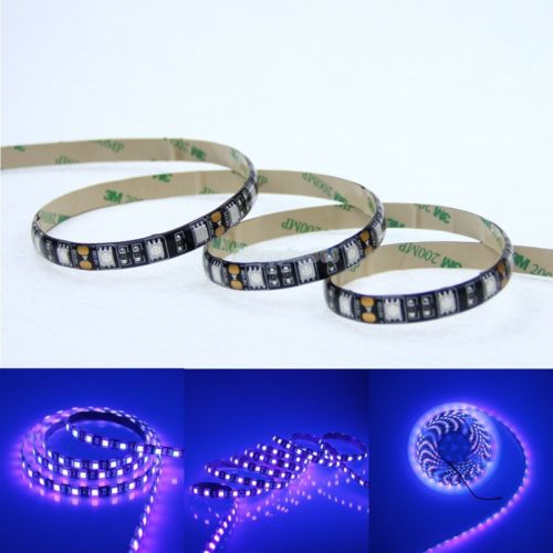
5M UV (395-405nm) waterproof 5050 SMD 300LED strip, powered by a 12 V @ 5 amp supply
The 5M long 5050 LED strips are 1cm in diameter and can be cut every 3rd LED. If they are cut into groups of 15 LEDs, this will result in 20 LED strips, each 25 cm long. Arranged side by side, this allows for creating a light source that will evenly expose a 20 cm x 25 cm area which is practically perfect for both A4 and 8x10in paper sizes. If one didn’t mind lower intensity it would be possible to left a 1cm gap between strips producing a source suitable for 16x20in / A3 paper, at the cost of longer exposure times.
When cutting the LED strip up, it is important to cut exactly in the middle of the metal contacts between every 3rd LED, as it will shortly be necessary to solder wires onto the metal contacts. If using the waterproof coated LED strip, the rubbery coating will have to be removed from the contact pads after cutting, which is quite tedious and an argument in favour of the non-waterproof variants. With the strip cut into pieces, it is now time to connect them back together by soldering short (5-10 cm length) wires between the metal pads. While it is possible to wire them all together in series to form one long strip, this means the link wires will be carrying the full 5 amp current load and if any link goes bad it risks taking out the entire set of LEDs beyond it. A better bet is to wire them up in parallel, or perhaps grouped in a mesh giving multiple paths for the current, so the link wires only need handle a tiny current and there is redundancy. The important thing when soldering the link wires is to preserve the polarity between strips – ie connect positive to positive, and ground to ground.
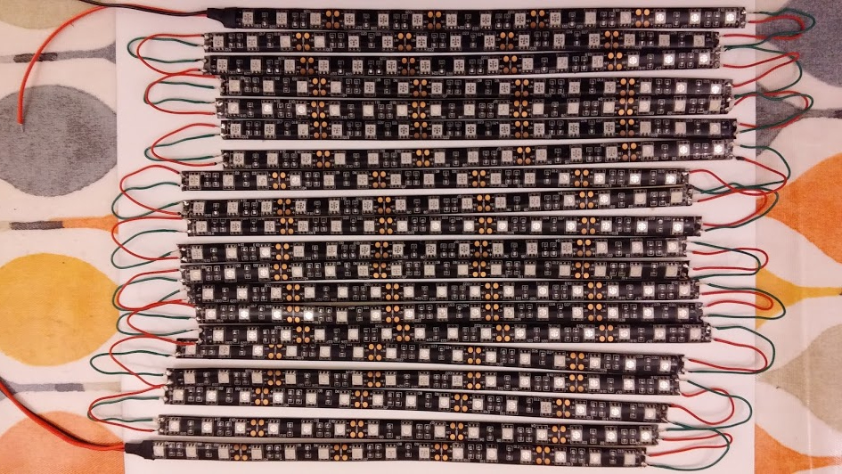
All 20 strips with connecting wires soldered on. Mistakenly all 20 strips are in series. This was later resoldered to split them in 5 groups of 4 strips, each group in parallel, reducing current in the link wires to 1amp.
The vendors of the LED strips will typically also sell suitable power supplies. These mains powered units need to output 12 volts and be capable of supplying 5 amps to enable the LEDs to run at full brightness. Lower amperage PSUs will work, but the reduced LED intensity will obviously increase exposure times, so it is best to simply get the right specification of PSU from the start.
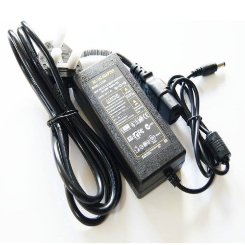
Mains PSU for the LED strip able to supply 12 volt at 5 amp
The power supply will likely have either a 2.5mm or 2.1mm plug, so a correspond matching socket needs to be purchased. While it is possible to just turn the device on/off at the wall, or by pulling the plug out, a better bet is to put a rocker switch inline with the positive power line between the plug socket and the LED strip. Again make sure the rocker switch is rated to carry 5 amps.
Power output is given by multiplying voltage by current, so 12 volt at 5 amps will produce 60 watts of power output. This is going to generate a reasonably large amount of heat and if something is not done about this, it will gradually degrade the LEDs shortening their lifetime. The obvious answer to this is to obtain a couple of 12 volt computer fans to fit in the case of the final light box. A fan that is approximately 4cm x 4cm in diameter will be ideal. They’re quite cheap so you might even consider using a pair of fans. The wires from the fan can be connected in parallel with the LED strips, since they’re conveniently driven from the same voltage. Do NOT connect them in series with the LEDs, as the 5 amp current draw of the LED circuit will kill the fans. Also be careful to get the positive/ground polarity right when connecting the fan, as reversing polarity will NOT make the fan run in reverse and likely kill the fan too.
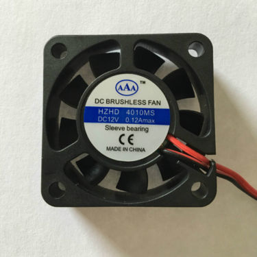
12 volt computer fan, 4cm in diameter
The case for the light box will be made out of wood and comprise two pieces, a base which will hold the paper to be exposed and a slightly larger lid which will hold the LED panel. Both will have sides and be sized so that the base nests snugly inside the lid (or vica-verca). The top and bottom panels can both be cut from a sheet of 3mm plywood, the lid panel being 39×30.5cm and the base panel 36.5×25.5cm. These sizes are fairly arbitrary – the smaller simply needs to be about 2 inches larger than the size of paper to be exposed on each side. So for 8×10 paper, the smaller would want to be about 12×14 inches. For the larger lid, sides were cut from a length of 70x18mm timber, and nailed to the plywood panel. For the smaller base, sides were cut from a length of 36x10mm timber. In the timber sides of the lid, two 4x4cm holes were cut to hold the fans. Two holes were also drilled in the lid, one for the power supply plug socket and the other for the on/off rocker switch. When inserting the fans in the case, one should be oriented so that it sucks air into the case while the other should blow air out of the case, creating good airflow across the LED panel.
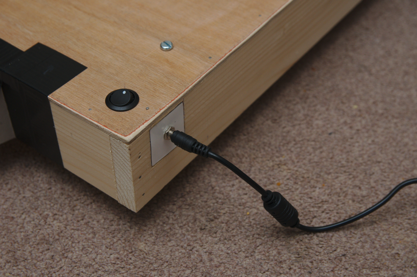
Light box lid showing the on/off rocker switch through the panel and power supply socket in the side
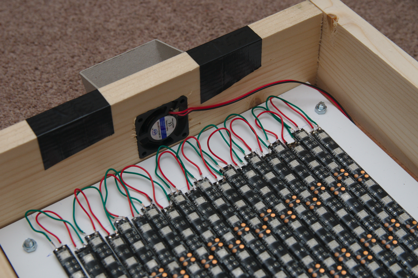
Close up of the lid, showing the computer fan inserted in the side to pull air across the LEDs for cooling.
The LED strip usually comes with a self-adhesive backing tape which is supposed to be able to stick the LEDs to most surfaces. This proved insufficiently sticky for me, so I applied super-glue instead. While the LED strips could be attached directly to the lid of the light box, it was thought preferable to attach them to a sheet of perspex or aluminium to allow the LED sheet to be separated from the case if needed. If using metal just be careful to avoid any short circuits with the link wires of the LED. Once the LEDs are attached, the sheet can be fixed to the inside of the lid with a couple of screws.
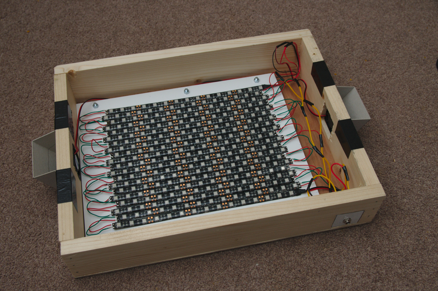
The larger lid, showing the metal plate with LED strips attached. At either end are cardboard shields to block UV light leakage through the fans.
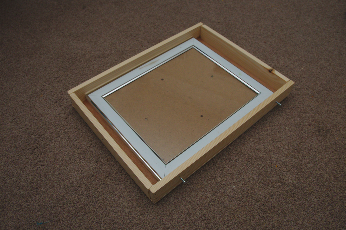
The smaller lightbox base, sized to be able to hold an 8×10 inch picture frame from a pound shop. Note a couple of screws sticking out of each side of the base, to prevent it sliding completely inside the lid when nested
When first turning it on, there was some UV light leakage through the cooling fans. Thus a couple of shields were cut from heavy duty cardboard and duct taped over the fan openings. With this in place there is no significant UV leakage from the light box, due to the closely nested lid and base. The UV LEDs are emitting at the end of the UVA spectrum, quite close to the start of the visible light spectrum, so the light is not a serious danger like UVB light would be, but it is none the less worth taking care to avoid accidental exposure.
In use the light box has proved to be intense enough to expose acceptable cyanotype images in as little as 5 minutes, and lumen images in anywhere from 10 minutes upwards depending on the visible effect desired. This is considerably faster than many commercially obtainable UV light sources that photographers have used in the past, which could take 15 to 30 minutes or even more. All together the cost of the complete box was probably around £45 – if you already have some parts in the shed such as plywood / timber pieces and a suitable power supply, then the price could be around £20-25. Either way, it will easily beat the cost of commercially produced light boxes and likely perform better too. The hardest part in construction is probably the soldering of the 50+ link wires between the LED strips. The case needs only minimal wood working skills – use of a saw and hammer. In summary creation of the light box is a very worthwhile use of time and money and will proof useful for years after.
Hi
Do you think you could post a pic / diagram of the correctly wired 5 groups of 4 strips so the current is split as can’t quite visualise how to do it.
Thanks!
Very nice Daniel
I have done something very similar. I used IKEA storage boxes, stuck the lights direct to the inside and wired each strip back to a single terminal. No fan as its on no longer than 5 minutes. I use a old Alarm 12volt battery, it lasts many uses before charging. As for light leakage, I cover with an old towel.
I put the box over the item and glass sheet, which just lays on the bench. For double sided I use 2 of them.
Steve
Hi,
Can you tell me the distance from the LED’s to the surface of the cyanotype paper?
The LEDs are pretty close, in the region of 3-5 cm, depending on what kind of clip frame I’m using to hold the paper in position.
Can you tell me what gauge wires you are using? The wire from the power source is larger (yellow) than the small red/green wires that are jumping from one strand of LEDs to the next, right?
I don’t recall what gauge the wire is. Just bear in mind that the overall current for the whole circuit is 5 amps, so the wires from the power source need to cope with that. I wired the LEDs into 5 parallel strips, so the links between strands only needed to cope with 1 amp, hence could be thiner.
Daniel, are you happy with the exposure using led’s vs sun? I’ve made the same lamp however I noticed that there much less detail on the print plus they are a little fuzzy? Have you noticed something like that?
Thanks,
Tomasz
There is definitely a difference between exposure with the sun vs LEDs, since the sun is fairly broad spectrum UV, while the LEDs only emit a very narrow wavelength. I can’t say I’ve made any direct comparisons of quality though. IME, fuzzy images are mostly caused by not having the digital negative in good contact with the paper. You want a good heavy sheet of glass clamped firmly to sandwich the paper and negative together.
Hi, thanks a lot for this guide! If I would like to make a larger unit, lets say: 50X60 cm, that means I need around 3 sets of 5 m. do I need also 3 electric supplies or wili 1 do for all?
Depending on how large you need it to be you could simply space out the LED strips. This would be good for a 25x40cm unit. The main change would be longer exposure times. Spacing them too much though, and the illumination might become uneven causing bad exposures, so that might require multiple strips of LEDs.
For a 50×60 you could probably get away with 2 sets of 5m. One strip requires a power supply that can deliver 5 amps at 12volts. So two strips would need a PSU capable of 10 amps. You would need to make sure to wire the in parallel too, otherwise the voltage drop will get too large and the current on individual wires would be too large too. It might end up being simpler to just use 2 separate PSUs. In fact if you’re very clever you could just make yourself 2 separate 50×30 cm exposure units that could be placed side-by-side for larger prints.
Hi,
I’m currently making one from your example. But there is something I don’t understand. The LEDstrip comes with two sides connection….but when using one, it seems enough. Why should I connect connect each strip from both sides? I’m thinking of making a negative strip and a positive and attach them from only one side. Saves me half of the soldering…but what if it was necessary??
Can you en-light me?…
Wouter
There’s no perfect answer here, but there is one wrong answer which I did originally :-) I first mistakenly wired them all together in series, as one long strip. This was a very bad idea as the links wires wouldn’t cope with 5amp current, and the voltage drop from to the end of the long strip would result in dimmer LEDs. So I simply broke some links to create 5 sets of 4 strips in parallel. It is perfectly valid to just put all 20 strips in parallel and thus only need to solder wires onto one end of each strip if you desire.
Thanks for the light in my darkness…
https://community.particle.io/t/when-i-connect-chain-of-led-strips-to-power-from-both-ends-do-i-need-to-make-the-power-line-disconnect-in-the-middle/35555/4
It almost gave me the same answer. And points out the voltage drop. I hope the difference isn’t to much, because then I have one side which takes a larger exposiontime then the other…..
And for the dummies among us: https://www.ledsupply.com/blog/guide-to-soldering-high-power-leds/
As far as I can see there is not an option for me to upload pictures in my reply, so maybe later on I post a link to the DIY-lower-budget I’m creating at the moment.
Thanks for now.
The voltage drop is only going to be significant if you have very long strips – eg the full 5 meter roll in one strip. By cutting it every 15 LEDs, and wiring up the strips in parallel the voltage drop won’t be significant enough to worry about.
Hello, Daniel! I’m so grateful for your instructions as I’ve been able to build a unit that works for my cyanotypes. I’d like to try to space the strips farther apart after learning that each LED light actually has a 120° LED beam angle. Depending on the height of the box sides (distance from the light strips to the negative – it might actually be possible to space them farther, in my case box height 4″ so the strips could be spaced 3 inches apart. I was wondering what you think about this as I’m getting ready to start a second unit- https://www.ecolocityled.com/downloads/light_diffusion_rgb_1.pdf
Thanks so much,
Angela Silva
Philippines
Yes, you can certainly space them further apart if desired. As well as giving you a larger area of exposure, you’ll improve the cooling as the LEDs won’t be in such a confined space. The only downside is that your exposure times will increase, so its a tradeoff between exposed area and exposure time.
Hi there, I built the same device and made some improvements, still work on a 2.0 version. the water resistant leds have a coating that can block the uv light over time for this purpose the non water resistant leds would be a better choice.
Yes, I found the same last year in fact. The waterproof coating went a yellowish colour over about 2 years to the point where it wouldn’t expose cyanotypes at all. I tediously stripped the waterproof coating off and it was as good as new, so definitely AVOID the waterproof LEDs.
I’ve since made a second box with some slight changes, first of which was that I bought a pre-built wooden box which saved alot effort. The other big change is that I didn’t use fans, instead I attached two large heatsinks on the back of the aluminium plate the LEDs are stuck too. They certainly conduct alot of heat away. Even better would be to then add fans on the heat sinks. This would give me confidence to run it continuously for hours.
Helllo, i was wondering if i could use this exposure unit, to expose my photo emulsion coated screens?
In theory it is good for anything which needs UV light exposure. Unless I’m misunderstanding what you’re asking though, photo emulsion though wants visible light, not UV.
Daniel, thanks for the very informative article. I’m planning on building one of these and was wondering what kind of pre-built box you used to build your second one and where did you buy it? Also what size was the box you used?
I’m planning on building one 40×50 cm for the grid size so I’ll need a box somewhat bigger than that. I also figured I’ll need 4 – 5m rolls since the area will be 4 times the one you built here, as I want to keep my exposure times short.
Thanks in advance for your response advice!
Randy
I tend to get pretty much everything off eBay. It was a wooden a4 box, typically advertized as for magazine/document storage. I’m not sure you’ll find any much bigger than that though.
Note one issue with using 4 rolls of LEDs will be the power supply and cooling requirements – a single roll requires a 12 V / 5 A PSU, so four rolls would require 12 V / 20 A, equiv to about 240 Watt. Finding a 20 A PSU brick will be significantly harder and more expensive. You’ll also need to install many many more fans than I used. 2 fans proved insufficient for even a single roll, so the second box used two huge and expensive heatsinks. I figure at least 4 fans per roll of LEDs, and/or fans and heat sinks combined. If ypou don’t get cooling good enough the LEDs will suffer damage from heat and burn out or fade
Hi, Thank you for the article! Very helpful.
1) I was curious, can I just sort of fold them around the corners rather than all the smoldering business, I could even tape the end blocking their light if the pucker that occurs creates some unevenness. Also, this isn’t something I am going to use a lot so I am thinking I may skip the fan and place them slightly further apart and expose for longer.
2) That said, my print is 46in x 38 in and you mention something in the comments about using multiple strips and the power supply, I was just going to plug them all into an outlet strip thing.
3) Would foiling the inside of the box help?
4) When you mention that outdoor UV light has a wider range – can you say how this impacts the end product? Like what is the loss on the end product doing it in a box?
Thank you very much!
Folding the LED strips around the corner is not a good idea. The voltage drops along the length of the LED strip, so the LEDs at the end are dimmer. IOW if you leave it in one long strip the intensity of UV exposure will vary across the print. Cutting the 5 meter long strip into short sections and soldering them up in parallel ensures the voltage drop is negligible.
If using multiple strips you need to be aware of the total current the LEDs want to draw. A single LED strip wants 5 amps to run at maximum brightness.. If your PSU can provide 5 amps maximum, then connecting two LED strips will result in them not getting the current they want. Thus the LEds will be dimmer and exposure times longer.
I don’t think foil will make a significant difference, as the LEDs are directly facing the prints and thus you don’t loose much light from reflections, or lack thereof.
I’ve not done any direct comparisons with natural UV source, as UV from the sun constantly changes based on time of year/day/weather. It’ll affect the contrast most likely, but this can be compensated for by preparing your negative in a suitable way. Essentially adjusting the negative density and using test strips to directly match it to your final UV exposure unit. Search for “cyanotype test strips” or similar to find guides on testing.
Hi there, great to find your post ….. I am in the midst of creating a box for UV lamp 80W for my cyanotypes … and wondering if you would recommend painting white or black inside so the sides can reflect or direct the light onto the light sensitised paper. Puzzling me lol. TIA
If using a traditional style UV lamp instead of LEDs, then yes, you’ll want to make the insides of the box reflective to ensure the light spreads out mokre evenly. Painting a silver colour is possibly best – the more shiny the better. Black is not what you want as that will absorb instead of reflecting.
Very interesting project and good construction! Which is the distance between the film/paper sandwich plane and the LED stripes plane? Thank you very much. Regards
Probably ends up being around 5 cm, but of course exact distance will depend on how big you make the box. I wouldn’t go much below 5cm as it probably wouldn’t allow enough diffusion of the light to get even illumination.