Category Archives: Projects

Building a Kodak Brownie digital camera

The Kodak Brownie was the first camera to really bring photography to the masses with a low purchase price. The simplicity of its design meant anyone could figure out how to use it with little difficulty – even by comparison with today’s cameras it is still easy to use, since it has essentially no controls to learn – just a shutter button, view finder and film winder. Millions of Kodak Brownies were made over the course of its 60 year lifespan, from 1900 onwards and the build quality & simplicity means many survive in good working order. The upshot is that a Kodak Brownie is a good option for custom modifications – easily available on ebay or in car boot sales, simple to hack and cheap enough that it doesn’t matter if things go wrong.

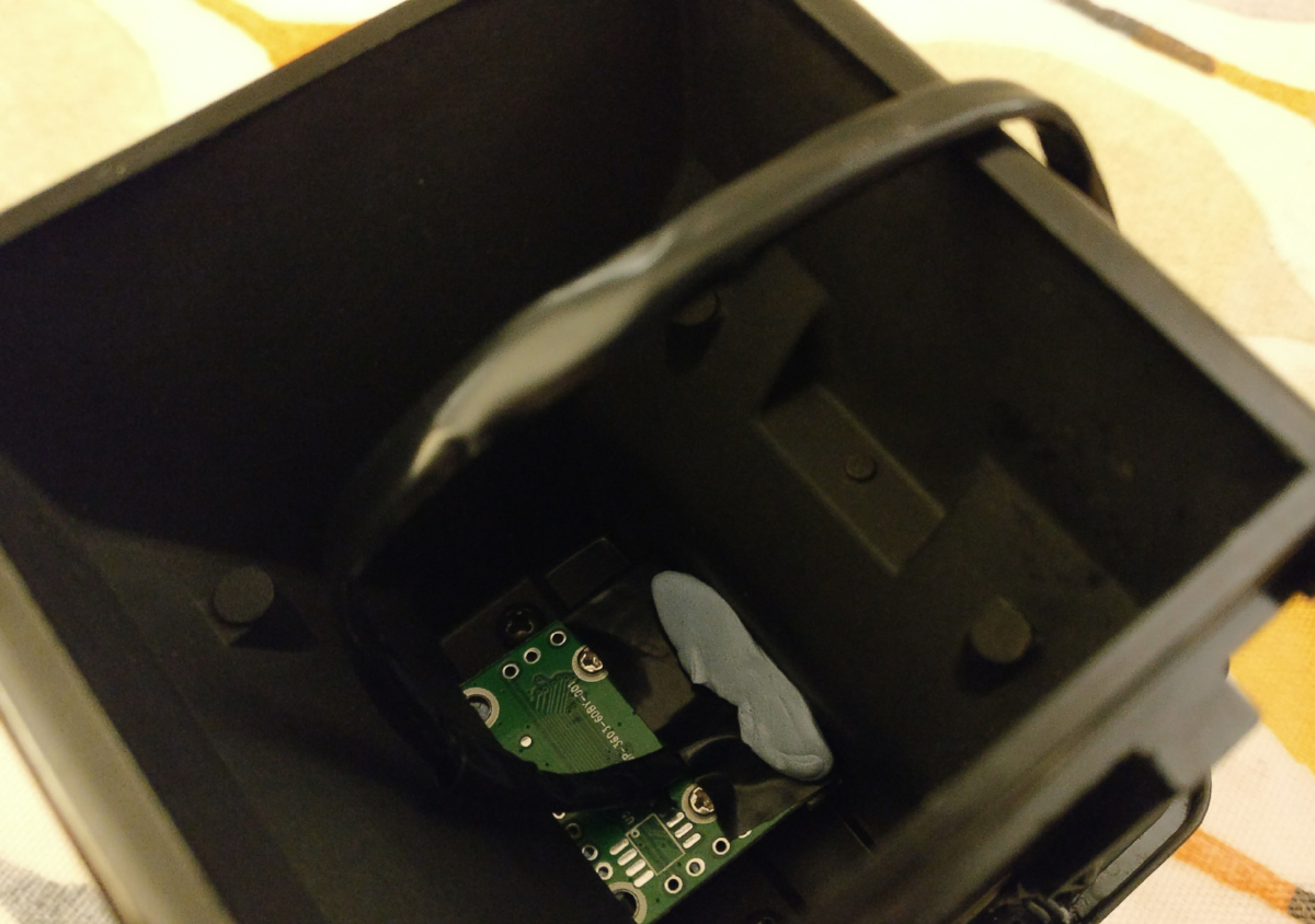
The original plan was to build a variant on my previous raspberry pi & webcam based pinhole digital camera, since I already had a second raspberry pi zero needing a purpose. A previous trip to the local carboot sale had yielded a Kodak Brownie Hawkeye for less than £5, which is the variant from the 1950’s with a case made out of bakelite instead of wood / cardboard. So the only key missing piece was a webcam. Since both the raspberry pi zero and kodak brownie had cost less than £5, that was set as the upper limit for obtaining a webcam. Trawling eBay listings found a number of sellers offering a variety of 50 megapixel cameras at this price point. These technical specs were clearly complete & utter lies – it was never going to be a 50 MP sensor for that price – but at the same time it was worth a punt to discover just what the cameras did offer. I first one I obtained turned out to provide 640×480, or a mere 0.3 MP with raw video only, no mjpeg, thus limiting the framerate too. IOW pretty awful, but only marginally more awful than expected. The plus side was that the case was easy to remove exposing a very compact circuit board which would be an ideal size for embedding.

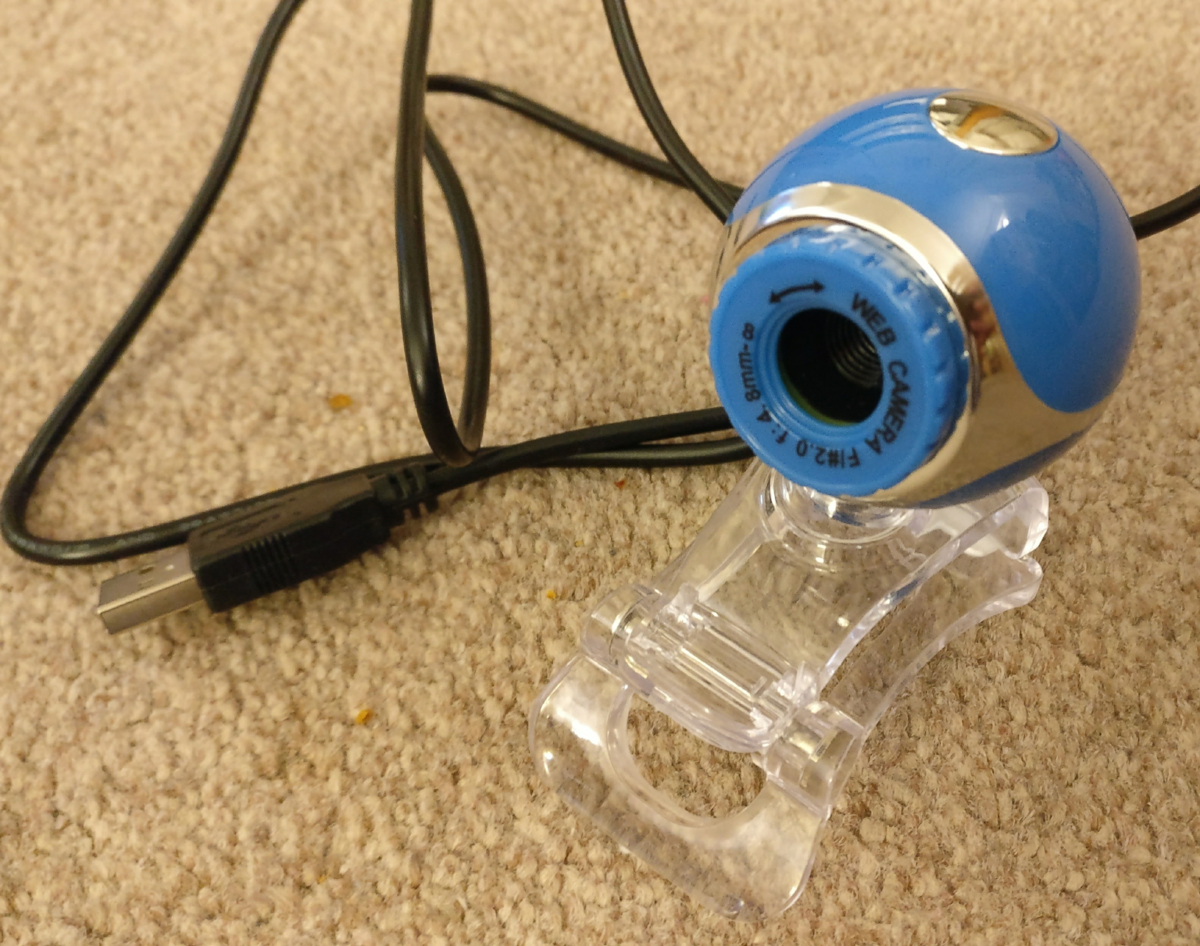
The “50 megapixel” eBay webcam, which turned out to be 0.3 megapixels, prior to removing the case

Upon testing the webcam with an improvised pinhole plate, it was clear that the sensor had unacceptably poor low-light performance. While it could serve as a pinhole camera, it would only be usable outside in bright conditions. I wanted to build a camera that was more versatile, so the plan was changed to build a “normal” digital camera instead of pinhole digital camera.

With the key parts obtained, design and assembly could begin. An initial approach was to keep the Brownie’s original lens and position the bare webcam sensor behind it. To achieve sharp focus, the sensor would have to be placed at the same position that the film would be relative to the lens. Each film negative, however, was 60x60mm in size, while the webcam sensor was less than 5x5mm. Testing confirmed that the webcam would have an incredibly narrow field of view, making it near impossible to compose shots with the crude viewfinder mirror.

The alternative was to disassemble the Brownie and remove its own plastic lens. The webcam circuit board could then be positioned such that its own lens was would be right behind the shutter. The circuit board was just a few mm to large to fit into the required position, so a dremmel tool was used to carve a slot in the inside of the case, allowing the circuit board to slip into place.

The interior of the Kodak Brownie, showing the circuit board in place immediately behind the lens. The circuit protrudes through a slot cut in the wall and held in place with bluetak.

This allowed the webcam to have a field of view similar to that of the original Brownie. In fact the field of view was wide enough that it covered the entire shutter aperture so the resulting images showed a circular vignette.

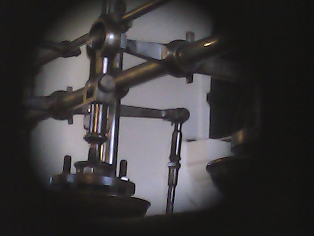
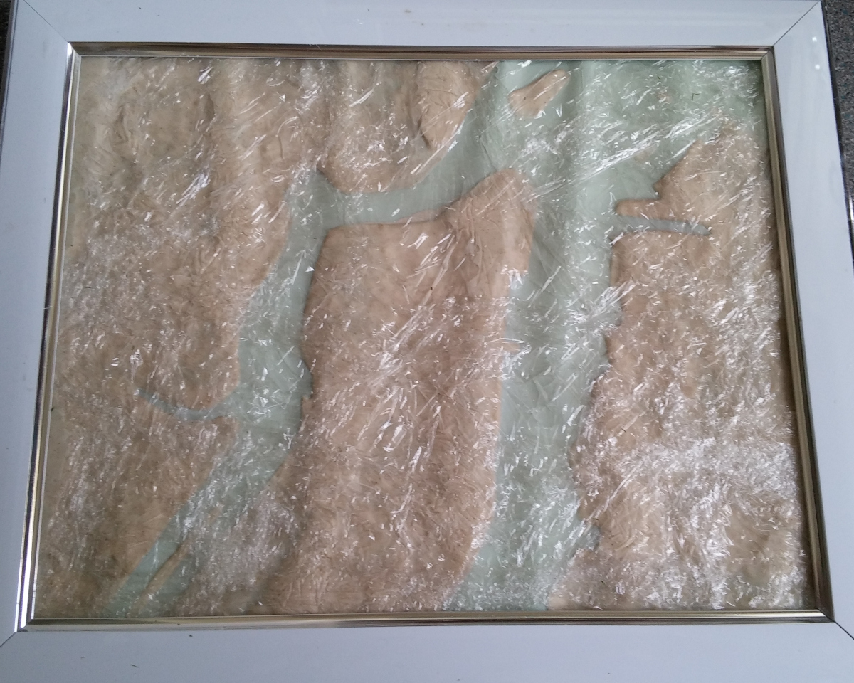
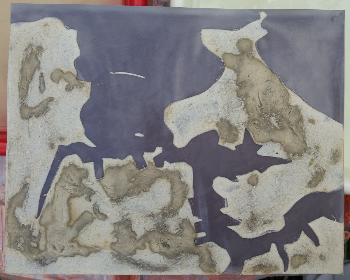
Still image captured by the webcam when behind the Kodak Brownie lens. The sensor field of view expands beyond the maximum size of the shutter aperture

The second task was deciding how to position to Raspberry Pi Zero in the case. As luck would have it, the width of the Pi Zero is exactly the same as the length of a 620 film spool, so the film holders were able to grip the Pi Zero circuit board. In common with the previous pinhole webcam, two LEDs were to be used, one illuminating when the power is on and one illuminating when the webcam is capturing an image. Two small holes were drilled in the top of the Brownie case next ot the shutter button, through which the LEDs could poke. A spot of superglue held the LEDs in the correct position.

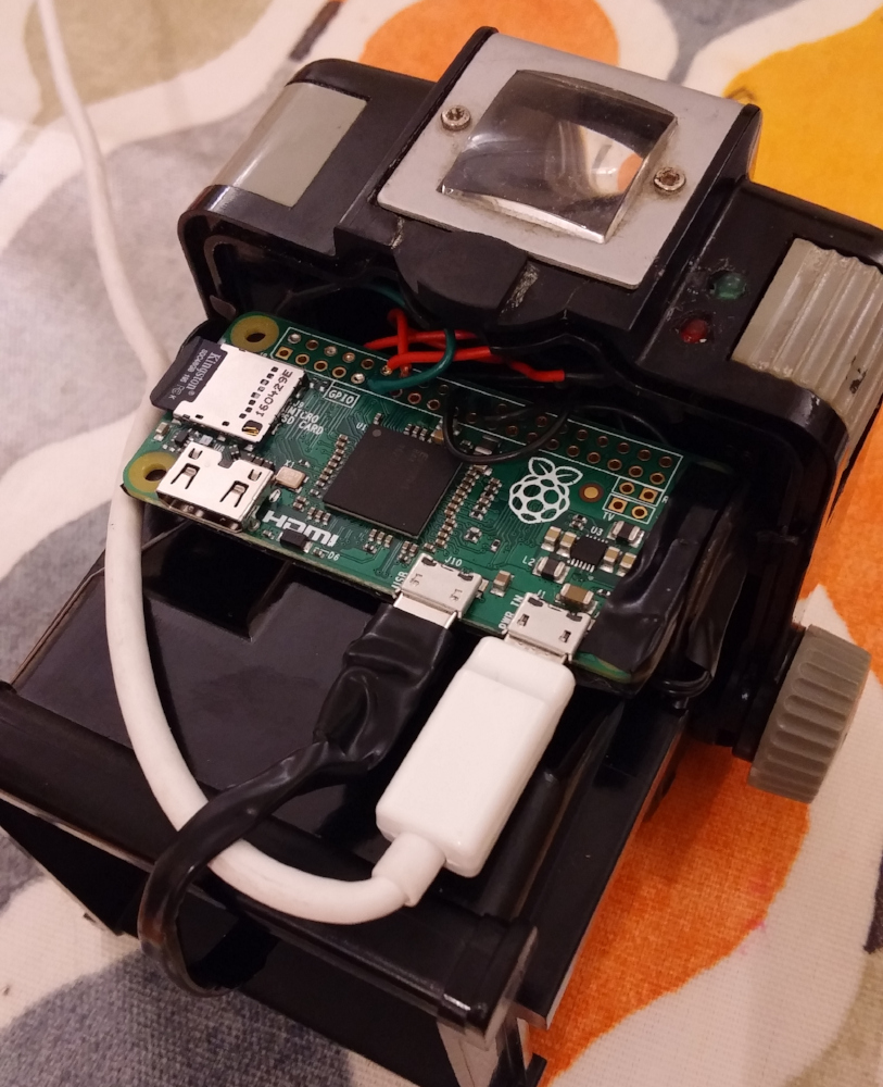
Inside of Brownie case showing the Raspberry Pi Zero board, USB power cable and LED status indicators

One of the key goals for the camera design was that the shutter button on the Kodak Brownie should be used to trigger image capture on the webcam. Ideally a single press of the shutter button would capture a single image. To achieve this, the mechanical shutter button needed to interface with the Raspberry Pi GPIO pins in some manner. After thinking about this tricky problem for a while, a solution involving a pair of bare wires and some conductive paint was conceived. One wire would connect to a programmable GPIO pin configured as an input in pull-up mode. The second wire would connect to a GPIO ground pin. A hole was drilled through the case coming out immediately below the shutter button, through which the wires could pass. Insulation was stripped off the wires and they were superglued in position below the shutter button. Finally a blob of conductive paint was applied to the underside of the shutter button. The result is that when the shutter button is pressed, the conductive paint shorts out the two wires, pulling the GPIO pin to ground. This change can be detected by the Pi Zero and used to trigger the shutter.

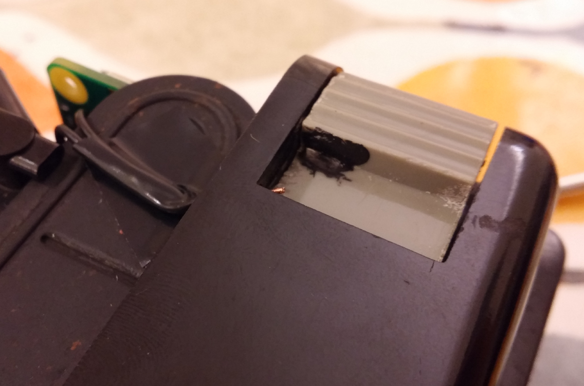
Shutter button on the Kodak Brownie, showing a blob of conductive paint, used to short circuit wires used to trigger webcam capture

The Brownie shutter mechanism is designed for film with a fixed shutter speed. It was not practical to synchronize image capture with the precise fraction of a second that the shutter was open. Fortunately the Brownie has a long exposure mode where the shutter remains open for as long as the shutter button is pressed. Normally this long exposure mode is activated by raising a second button on the Brownie, but this is somewhat tedious. A little bit of electrical tape applied to the shutter mechanism was able to hook it into permanent long exposure mode.

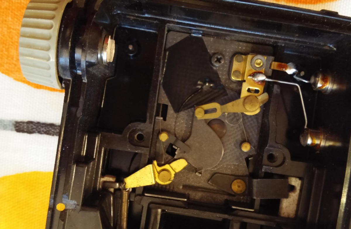
The Brownie shutter mechanism with spot of electrical tape used to fix it in long exposure mode permanently.

Testing of the shutter mechanism was revealed a small problem – the webcam takes  a second or two to automatically measure & adjust exposure to suit the lighting conditions. The result was that if an image was captured immediately after pressing the shutter button, it would often be totally underexposed. This prompted another slight change in design. Rather than capturing a single image immediately as the shutter is pressed, the software was written to wait a second after shutter press and then capture images continuously thereafter, one per second, until the shutter was released. IOW, it would be a timelapse capture device.

The only remaining task was power. The Pi Zero and webcam combination has very low power requirements, at most 200 milliamps, and it was already known that a USB lithium ion powerpack provides an excellent power source that lasts a really long time. The problem is that for most powerpacks on sale today, physical size is not a hugely important factor. To date it has been impossible to find one that is small enough to fit inside the Brownie case – it would need to have a longest dimension of 6cm to stand a chance of fitting once the USB cable is plugged in – 5cm would be even better. Having the battery inside the case also adds a requirement to put a physical power switch between the Pi Zero and the battery, unless you want to open the camera to turn it on/off every time. The simple solution was thus to just drill a hole in the case for the USB cable, leaving the battery on the outside.

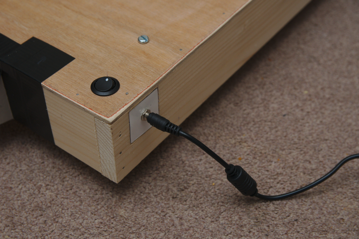
Finished Kodak Brownie digital camera showing cable to external battery pack

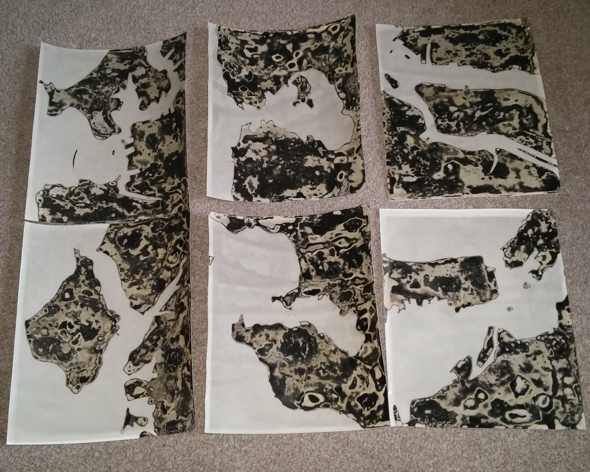
With the hardware construction complete, attention turned to the software to control it. Rather than start from scratch, the previous code used for the pinhole webcam Arcturus, was used extended. First it was discovered that the cheap webcam didn’t provide MJPEG capture, which meant pulling in libjpeg to do encoding of the raw frames into JPEG still image files. Capturing images in raw format means the USB device has to transfer far larger quantities of data. While this wasn’t a problem on the laptop used for development, the raspberry pi was continually getting dropped / incomplete frames from the webcam. After countless hours debugging, the problem was discovered to be the driver for the USB controller in Linux mainline, used by Pignus (the Fedora fork for the Raspberry Pi arm6 borads). The Raspbian kernel by comparison has an out of tree driver for the USB controller which turned out to work fine. The remaining software changes involved wiring up support for using the shutter button to trigger capture via a GPIO pin. The end result was that upon pressing the shutter button it would capture still images continuously, 1 per second. After a sufficiently long series of stills had been captured, they could be turned into a timelapse video sequence.

Building a UV LED light box for cyanotype and lumen printing

The cyanotype and lumen printing processes are two of the more frequently practised alternative photographic processes, because of their overall simplicity and the fact there is little-to-no need for equipment. Most people will do their exposures outside in the Sun initially, but if you want to work with these processes on a regular basis it can be frustrating to have ideas ready to try, but be delayed by lack of a sunny day. While it is still possible to expose on cloudy days, the length of time required to obtain a suitable image is greatly increased. Working with the sun it is also difficult to figure out predictable exposure times as the intensity varies according to the daily weather, time of day and time of year.

The solution is to switch to an artificial UV light source which can be used any time of day or year, whatever the weather, always giving the same exposure time. Historically though, UV exposure units have been relatively expensive to obtain, £100 or more. The ongoing developments in LED lighting technology though have now opened up new possibilities for constructing a custom UV light source for minimal cost. In particular it is possible to obtain 5m long strips holding 300 UV LEDs from online marketplaces such as eBay, for around £15 / $20 (search eBay for keywords “5M UV 5050 SMD 300LED“).

 5M UV (395-405nm) waterproof 5050 SMD 300LED strip, powered by a 12 V @ 5 amp supply

5M UV (395-405nm) waterproof 5050 SMD 300LED strip, powered by a 12 V @ 5 amp supply

The 5M long 5050 LED strips are 1cm in diameter and can be cut every 3rd LED. If they are cut into groups of 15 LEDs, this will result in 20 LED strips, each 25 cm long. Arranged side by side, this allows for creating a light source that will evenly expose a 20 cm x 25 cm area which is practically perfect for both A4 and 8x10in paper sizes. If one didn’t mind lower intensity it would be possible to left a 1cm gap between strips producing a source suitable for 16x20in / A3 paper, at the cost of longer exposure times.

When cutting the LED strip up, it is important to cut exactly in the middle of the metal contacts between every 3rd LED, as it will shortly be necessary to solder wires onto the metal contacts. If using the waterproof coated LED strip, the rubbery coating will have to be removed from the contact pads after cutting, which is quite tedious and an argument in favour of the non-waterproof variants. With the strip cut into pieces, it is now time to connect them back together by soldering short (5-10 cm length) wires between the metal pads. While it is possible to wire them all together in series to form one long strip, this means the link wires will be carrying the full 5 amp current load and if any link goes bad it risks taking out the entire set of LEDs beyond it. A better bet is to wire them up in parallel, or perhaps grouped in a mesh giving multiple paths for the current, so the link wires only need handle a tiny current and there is redundancy. The important thing when soldering the link wires is to preserve the polarity between strips – ie connect positive to positive, and ground to ground.

All 20 strips with connecting wires soldered on. Mistakenly all 20 strips are in series. This was later resoldered to put them in parallel

All 20 strips with connecting wires soldered on. Mistakenly all 20 strips are in series. This was later resoldered to split them in 5 groups of 4 strips, each group in parallel, reducing current in the link wires to 1amp.

The vendors of the LED strips will typically also sell suitable power supplies. These mains powered units need to output 12 volts and be capable of supplying 5 amps to enable the LEDs to run at full brightness. Lower amperage PSUs will work, but the reduced LED intensity will obviously increase exposure times, so it is best to simply get the right specification of PSU from the start.

Mains PSU for the LED strip able to supply 12 volt at 5 amp

Mains PSU for the LED strip able to supply 12 volt at 5 amp

The power supply will likely have either a 2.5mm or 2.1mm plug, so a correspond matching socket needs to be purchased. While it is possible to just turn the device on/off at the wall, or by pulling the plug out, a better bet is to put a rocker switch inline with the positive power line between the plug socket and the LED strip. Again make sure the rocker switch is rated to carry 5 amps.

Power output is given by multiplying voltage by current, so 12 volt at 5 amps will produce 60 watts of power output. This is going to generate a reasonably large amount of heat and if something is not done about this, it will gradually degrade the LEDs shortening their lifetime. The obvious answer to this is to obtain a couple of 12 volt computer fans to fit in the case of the final light box. A fan that is approximately 4cm x 4cm in diameter will be ideal. They’re quite cheap so you might even consider using a pair of fans. The wires from the fan can be connected in parallel with the LED strips, since they’re conveniently driven from the same voltage. Do NOT connect them in series with the LEDs, as the 5 amp current draw of the LED circuit will kill the fans. Also be careful to get the positive/ground polarity right when connecting the fan, as reversing polarity will NOT make the fan run in reverse and likely kill the fan too.

12 volt computer fan, 4cm in diameter

12 volt computer fan, 4cm in diameter

The case for the light box will be made out of wood and comprise two pieces, a base which will hold the paper to be exposed and a slightly larger lid which will hold the LED panel. Both will have sides and be sized so that the base nests snugly inside the lid (or vica-verca). The top and bottom panels can both be cut from a sheet of 3mm plywood, the lid panel being 39×30.5cm and the base panel 36.5×25.5cm. These sizes are fairly arbitrary – the smaller simply needs to be about 2 inches larger than the size of paper to be exposed on each side. So for 8×10 paper, the smaller would want to be about 12×14 inches. For the larger lid, sides were cut from a length of 70x18mm timber, and nailed to the plywood panel. For the smaller base, sides were cut from a length of 36x10mm timber. In the timber sides of the lid, two 4x4cm holes were cut to hold the fans. Two holes were also drilled in the lid, one for the power supply plug socket and the other for the on/off rocker switch. When inserting the fans in the case, one should be oriented so that it sucks air into the case while the other should blow air out of the case, creating good airflow across the LED panel.

Light box lid showing the on/off rocker switch through the panel and power supply socket in the side

Light box lid showing the on/off rocker switch through the panel and power supply socket in the side

Close up of the lid, showing the computer fan inserted in the side to pull air across the LEDs for cooling.

The LED strip usually comes with a self-adhesive backing tape which is supposed to be able to stick the LEDs to most surfaces. This proved insufficiently sticky for me, so I applied super-glue instead. While the LED strips could be attached directly to the lid of the light box, it was thought preferable to attach them to a sheet of perspex or aluminium to allow the LED sheet to be separated from the case if needed. If using metal just be careful to avoid any short circuits with the link wires of the LED. Once the LEDs are attached, the sheet can be fixed to the inside of the lid with a couple of screws.

The larger lid, showing the metal plate with LED strips attached. At either end are cardboard shields to block UV light leakage through the fans.

The light box base

The smaller lightbox base, sized to be able to hold an 8×10 inch picture frame from a pound shop. Note a couple of screws sticking out of each side of the base, to prevent it sliding completely inside the lid when nested

When first turning it on, there was some UV light leakage through the cooling fans. Thus a couple of shields were cut from heavy duty cardboard and duct taped over the fan openings. With this in place there is no significant UV leakage from the light box, due to the closely nested lid and base. The UV LEDs are emitting at the end of the UVA spectrum, quite close to the start of the visible light spectrum, so the light is not a serious danger like UVB light would be, but it is none the less worth taking care to avoid accidental exposure.

In use the light box has proved to be intense enough to expose acceptable cyanotype images in as little as 5 minutes, and lumen images in anywhere from 10 minutes upwards depending on the visible effect desired. This is considerably faster than many commercially obtainable UV light sources that photographers have used in the past, which could take 15 to 30 minutes or even more. All together the cost of the complete box was probably around £45 – if you already have some parts in the shed such as plywood / timber pieces and a suitable power supply, then the price could be around £20-25. Either way, it will easily beat the cost of commercially produced light boxes and likely perform better too. The hardest part in construction is probably the soldering of the 50+ link wires between the LED strips. The case needs only minimal wood working skills – use of a saw and hammer. In summary creation of the light box is a very worthwhile use of time and money and will proof useful for years after.

Obsolete and Discontinued: a collective photographic project

The project background

This post is talking about my involvement in the Obsolete & Discontinued project which has just had its first exhibition at the Releva-T analogue photography festival in Spain. The seeds of the project were sown back in March 2015, when London based photographer & expert printer, Mike Crawford, was given a huge quantity of photographic paper (and a few rolls of film) by a client, David Yates. The paper had come from darkroom supplies left by David’s late uncle, Bret Sampson. There was quite a variety of paper, including Agfa Record Rapid, Kodak Bromesko, Agfa Brovira, Kodak Royal, Kentmere Bromide, Ilford Ilfomar and more besides. Most of the paper was so old – at least 20 years, perhaps as much as 40 years for some – that common opinion would suggest it to be mostly worthless and fit only for the rubbish. Thankfully Milke did some test prints to investigate the condition of the paper, finding some in fine condition, while others had heavy fog. Even those which had heavy fog turned out to be quite amenable to lith developer which was not nearly as badly affected.

After seeing these results, Mike unveiled a proposal to a meeting of the London Alternative Photography Collective (LAPC) meeting. He intended to give out batches of paper (~10-20 sheets per person depending on number of participants) to a group of photographic artists with an open brief to produce any type of work they wished. The only rule was for the supplied paper to be used in some manner, whether for the final work or just in an intermediate step. The idea was immediately appealing and many attendees of that meeting signed up to participate in the project straight away, myself included. After getting around 60 people signed up Mike sent out details on what paper was available (and its response with test prints) to all participants asking them to provide a preference list.

Developing the techniques & idea

At the time, having a 3 month old baby, I wasn’t really going into the darkroom at all, so using any kind of traditional black & white process was out of the question, never mind learning lith printing techniques. I decided to focus on alternative photographic printing techniques that could be done without any use of a darkroom, specifically the lumen and chemigram processes which I had recently started experimenting with in the back garden. I had trays suitable for 8×10 paper and wanted FB paper rather than RC. Beyond that I was not fussed on the choice, whether it was fogged or not, since this is pretty much irrelevant to the chemigram process which takes place in full light. Essentially any photographic paper will work for chemigrams no matter how old or badly looked after it is. Eventually I was given approx 15 sheets of Agfa Brovira G3 as the official paper to use for the project work.

Rather than risk wasting this precious paper, I bid on a couple of ebay auctions acquiring some ancient kodak and ilford papers for exploration of the techniques I wanted to use in the project. With the ilford paper I learnt how to combine the lumen and chemigram processes to create very pleasing hybrid works. Showing one of the works to some friends at another LAPC meeting, a remark was made that one of the prints (shown below) gave the impression of a river running through a city:

Resulting print after combining the chemigram and lumen processes.

Resulting print after combining the chemigram and lumen processes.

I myself felt that the dark brown / black texture of the print felt like a desolate landscape, devastated by industrial development or some natural disaster – quite representative of the state (reckless) human development can leave land in. At the same time I was feeling that too many chemigram images I’ve seen focused on the totally abstract and so wanted to explore how to control the chemigram process to bring in more recognisable forms.

Melding these thoughts together, my intent for the Obsolete & Discontinued project was to try to produce semi-abstract, but still recognisable, images of coastal cities around the world using the chemigram and lumen processes.

Behind the scenes

The starting point was to identify some coastal cities whose border between land and sea would give rise to reasonably recognisable outline and a good balance. In other words I spent a while browsing around Google maps looking at coastlines for random cities I’ve visited in the past. This identified a number of candidates including London (Isle of Dogs), Southampton (Isle of Wight), Plymouth, New York, Boston, San Francisco, Rio de Janeiro and Tokyo. With these identified I printed out the maps on plain paper and using a scalpel cut around the coastline to remove the land

Printed map outline after cutting away the land mass

Printed map outline after cutting away the land mass

The paper outlines were then traced onto pieces of 2mm thick card, then cut out with a scalpel again, to create the master heavyweight stencils

Cardboard stencil after being traced and cut from the paper outline

Cardboard stencil after being traced and cut from the paper outline

The purpose of the stencil is to assist in applying the resist for the chemigram process. The chosen resist was a thick paste of flour and water, the same that was used in earlier chemigram experiments. The stencil was placed on a sheet of the photographic paper and the resist spread on in a thin layer. The ultimate result was that flour paste adhered to the paper in the regions that would represent the land mass, while the sea remained clear.

Applying a resist of flour & water to the photographic paper, using the cardboard stencil

Applying a resist of flour & water to the photographic paper, using the cardboard stencil

The coated paper is then left overnight to allow the flour paste to dry out and form a hard crust on the paper. With the areas representing the sea still exposed, it was time to start on the lumen processing. The idea was to try to get an abstract texture to represent the rippling surface of the sea. To this end, several layers of crinkled clingfilm were placed over the paper in a random fashion, which would (in theory) control the amount of UV light affecting the paper.

Paper covered in clingfilm and placed in a photo frame ready for exposure under the sun

Paper covered in clingfilm and placed in a photo frame ready for exposure under the sun

The paper was placed in a budget photo frame obtained from a local pound shop (aka dollar store) and then left out under the autumn sun for approx 4-5 hours. The UV light had quite a nice affect on the paper turning it a fairly intense purple/blue color, and the use of cling film had been partially successful in introducing variation in the colouration.

The paper after it had been exposed to the sun for several hours

The paper after it had been exposed to the sun for several hours

The lumen exposure was immediately preserved by putting the paper through a regular fixer bath. Sadly with the Agfa Brovira paper, almost all of the colouration from the lumen exposure disappeared. This is entirely expected when fixing lumen prints, but the degree of fading varies across different papers and the Brovira seemed particularly badly affected. The final step was to slowly dissolve away the flour resist, moving the paper between developer and fixer baths every 10 minutes or so. Where the developer came in contact with the surface of the paper first, it would go dark gray/black, while the fixer would preserve undeveloped areas in pale brown. In this way the texture was gradually built-up as the flour resist dissolved. The chemigram stage took at least an hour of hard work per print to complete.

In the end six prints were made on the Agfa Brovira paper supplied for the project, and the three most successful ones were selected for presentation to the project.

Final results of the process on Agfa Brovira paper

Final results of the process on Agfa Brovira paper

My time producing prints for the project spanned a couple of months, with me snatching 2-3 hours at a time to work on it when the weather was favourable to lumen printing, in between the usual time consuming duties of parenting. The most time intensive part was the chemigram process where the dried flour paste would very slowly dissolve, but the results obtained were certainly worth the effort. Participating in the project helped focus the mind, allowing for intensive effort to control & master a particular set of techniques, with a clear target in mind. It has been a great learning experience and I’m very pleased to have gotten involved in it.