The SkyWatcher Star Adventurer mount is a good quality equatorial tracking mount for DSLR based astrophotography. It is reasonably portable, so combined with a sturdy tripod, it is well suited for travel when weight & space are at a premium. It is not restricted to night time usage either, providing an option for tracking the movement of The Sun, making it suitable for general solar imaging / eclipse chasing too.
The key to getting good results from any tracking mount is to take care when doing the initial setup and alignment. The Star Adventurer comes with an illuminated polar scope to make this process easier. The simple way to use this is to rotate it so that the clock positions (3, 6, 9, 12) have their normal orientation, and then use a smart phone application to determine where Polaris should appear on the clock face. The alternative way is to use the date / time graduation circles to calculate the positioning from the date and time. Learning this process is helpful if your phone batteries die, or you simply want to avoid bright screens at night time.
The explanation of how to use the graduation circles in the manual is not as clear as it should be though, so this post attempts to walk through the process with some pictures along the way.
Observing location properties
The first thing to determine is the longitude & latitude of the observing location, by typing “coordinates <your town name>” into Google. In the case of Minneapolis it replies with
44.9778° N, 93.2650° W
93.2650° W - 90° W == 3.2650° W
Rough tripod alignment & mount assembly
Even though the Star Adventurer is a small portable mount, the combination of the mount, one or more cameras, and lens / short tube telescopes will have considerable weight. With this in mind, don’t try to get away with a light or compact tripod, use the strongest and heaviest tripod that you have available to support it well. When travelling, a trade off may have to be made to cope with luggage restrictions, which in turn can limit the length of exposures you can acquire and/or make it more susceptible to wind and vibrations. To increase the rigidity of any tripod, avoid fully extending the legs and keep them widely spaced. If the tripod has bracing between the legs use that, and if possible hang a heavy object beneath the tripod to damp any vibrations.
With the tripod erected, the first step is to attach the equatorial wedge. The tripod should be oriented so that the main latitude adjustment knob on the wedge is pointing approximately north. Either locate Polaris in the sky, or use a cheap hand held compass, or even a GPS app on a smart phone to determine north.
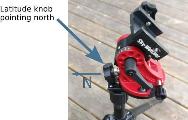 At this time also make sure that the two horizontal adjustment knobs are set to leave an equal amount of slack available in both directions. This will be needed when we come to fine tune the polar alignment later.
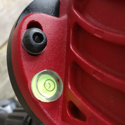
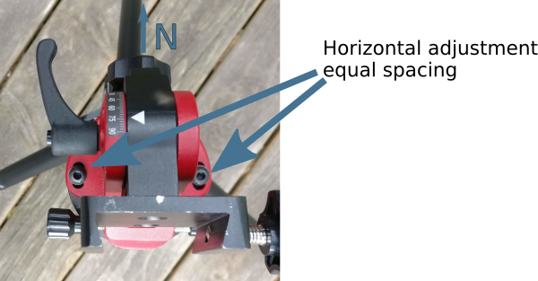 Now adjust the tripod legs to make the base of the wedge level, using the built-in omnidirectional spirit level to gauge it.
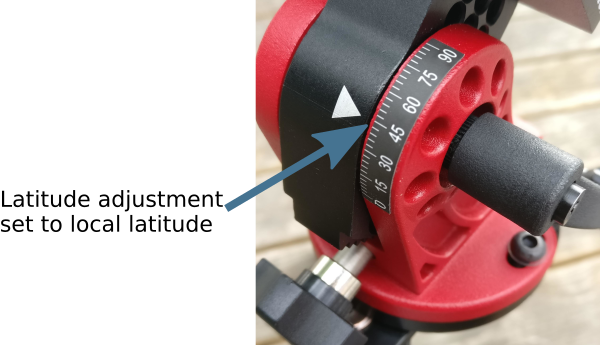
The final part of the approximate alignment process is to use the altitude adjustment knob on the wedge to set the angle to match the current observing location latitude. As noted earlier the latitude of Minneapolis is 44.9778° N, so the altitude should be set to 45 too. Each major tick in the altitude scale covers 15°, and is subdivided into 5 minor ticks each covering 3°.
At this point the main axis of the mount should be pointing near to the celestial north pole, but this is not anywhere near good enough to avoid star trailing. The next step will to do the fine polar alignment.
Checking polar scope pattern calibration
For a mount that has not yet been used, it is advisable to check the calibration of the polar scope pattern, as it may not be correct upon delivery, especially if the unit has been used for demo purposes by the vendor or was a previous customer return. Once calibrated, it should stay correct for the lifetime of the product, so this won’t need repeating every time. Skip to the next heading if you know the pattern is correctly oriented already.
The rear of the main body has two graduated and numbered circles tracking time and date. The outer circle is fixed against the body and marked with numbers 0-23. Each of the large graduation marks represents 1 hour, while the small graduation marks represent 10 minutes each. The inner circle rotates freely and is marked with numbers 1 through 12. Each of the large graduation marks represents 1 month, while the small graduation marks represent approximately 2 days each. The inner circle has a second scale marked on it, with numbers 20, 10, 0, 10, 20 representing the time meridian offset in degrees. The eyepiece has a single white line painted on it which is the time meridian indicator.
To check calibration the inner circle needs to be rotated so that the time meridian circle zero position aligns with the time meridian indicator on the eyepiece.
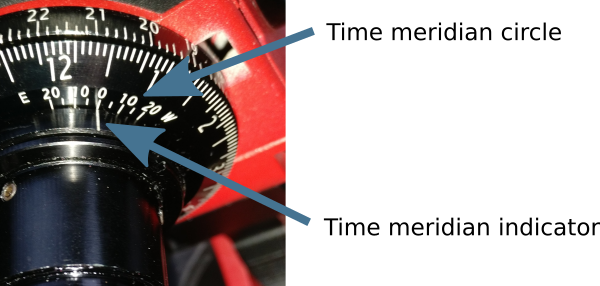
The zero position on the time meridian circle is aligned with the time meridian indicator mark on the eyepiece.
Now while being careful not to move the inner circle again, the mount axis / eyepiece needs to be rotated so that the zero mark on outer time graduation circle aligns with the date graduation circle Oct 31st mark (the big graduation between the 10 and 11 numbers).
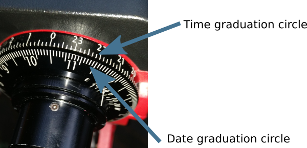
While not moving the inner cicle, the mount axis / eyepiece is rotated so that the number zero on the time graduation circle lines up with the large graduation between the 10 and 11 marks on the date graduation circle.
These two movements have set the mount to the date and time where Polaris will be due south of the north pole. Thus when looking through the eyepiece, the polar alignment pattern should appear with normal orientation, 6 at the bottom, 9 to the left, 3 to the right and 0 at the top. If this is not the case, then a tiny allen key needs to be used to loosen the screws holding the pattern, which can then be rotated to the correct orientation.
As mentioned above this process only needs to be done once when first acquiring the mount. Perhaps check it every 6-12 months, but it is very unlikely to have moved unless the screws holding the pattern were not tightened correctly.
Polar alignment procedure
After getting the tripod setup with the wedge attached and main body mounted, the process of polar alignment can almost begin. First it is recommended to attach the mount assembly dovetail bar and any cameras to the mount body. It is possible to attach this after polar alignment, but there is the risk of movement on the mount which can ruin alignment. The only caveat with doing this is that with many versions of the mount it is impossible to attach the LED polar illuminator once the dovetail is attached. Current generations of the product ship an shim to solve this problem, while for older generations an equivalent adapter can be created with a 3-d printer and can often be found pre-printed on ebay.
Earlier the difference in longitude between the timezone meridian and the current observing location was determined to be 3.2650° W. The inner graduated disc on the mount needs to be rotated so that the time meridian indicator on the eyepiece points to the time meridian circle position corresponding to 3.2650° W
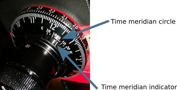
The time meridian indicator is aligned with the time meridian circle position corresponding to 3 W, which is the offset between the current observing location and the timezone meridian.
Now without moving the inner dial the main mount axis / eyepiece needs to be rotated to align the time graduation circle with the date graduation circle to match the current date and time. It is important to use the time without daylight saving applied. For example if observing on May 28th at 10pm, the time graduation circle marking for 21 needs to be used, not 22. May is the 5th month, and with each small graduation corresponding to 2 days, the date graduation circle needs to aligned for the graduation just before the big marker indicating June 1st.
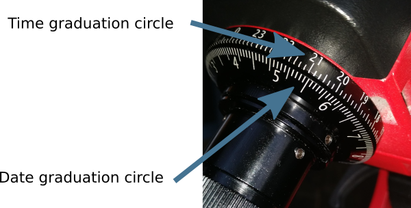
The time graduation circle marking for 21 is aligned with the date graduation circle marking for May 28th.
The effect of these two movements is to rotate the polar scope pattern so that the 6 o’clock position is pointing to where Polaris is supposed to lie. Hopefully Polaris is visible through the polar scope at this point, but it is very unlikely to be at the right position. The task is now to use the latitude adjustment knob and two horizontal adjustment knobs to fine tune the mount until Polaris is exactly at the 6 o’clock position on the pattern.
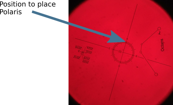
View of pattern through polar scope when set for 10pm on May 31st in Minneapolis, which is almost completely upside down. Polaris should be placed at the 6 o’clock position on the pattern.
Notice that the polar scope pattern has three concentric circles and off to the side of the pattern there are some year markings. Polaris gradually shifts from year to year, so check which of the concentric rings needs to be used for the current observing year.
The mount is now correctly aligned with the North celestial pole and should accurately track rotate of the Earth to allow exposures several minutes long without stars trailing. All that remains is to turn the power dial to activate tracking. One nice aspect of equatorial mounts compared to alt-az mounts, is that they can be turned off/on at will with no need to redo alignment. When adding or removing equipment, however, it is advisable to recheck the polar scope to ensure the mount hasn’t shifted its pointing.

How can i alig my star tracker at Quito Ecuador. My latitud is 0 degrees! Y cant never see the north polaris or the austral polaris, please helpme
I’m afraid I’m not sure how to deal with that – perhaps try asking one of the popular astronomy forums for suggestions as I’m sure there’s other people who will have figured out what todo.
Great article! I was not wanting to use an app and wanted to learn what all these dials meant. Question though: how do I know where to put Polaris on the circle? Or does it go where the 6 is after I do the adjustment?
Thanks in advance!
Cody
Yes, after orientating the polar scope you just place polaris at the 6 o’clock position.
Thanks for this article very useful. How do you check polaris alignment after putting equipment on to the mount when the equipment will block the alignment scope. You can probably see through the dovetail L-Bracket, but can’t attach the provided illuminator with the L-Bracket in place. I’m assuming there is no way to re-check alignment at all if you use the ball head adaptor with no L-Bracket as it blocks the scope view. The mount can take supposedly 5kg, but I’m sure loading it with any where near that is going to pull it out of alignment so is this just a design flaw with this piece of equipment? Any tips in this regard?
You definitely want to attach all your equipment to the mount before doing the fine polar alignment.
With my StarAdventurer this was impossible because there was no way to attach the polar illuminator once you have the dovetail rail on. This was/is a well know design flaw in the StarAdventurer to the extent that people 3d printed adapters to make it possible. I bought this one:
http://www.astrokraken.fr/polar-illuminator-adapter-for-star-adventurer-and-star-adventurer-mini-a129492988
I hear rumours that the current StarAdventurers actually fix this problem so no longer require the adapters, but I’ve not seen evidence of that firsthand.
My star adventurer came with a circle bracket with rectangle shaped prongs on it. You plug the illuminator into the other side without the prongs. Then you plug the prong side into the dovetail.
Sounds similar to the 3d printed adapter I acquired on ebay, so it is good to know they’re actually shipping this as standard now.
Once again thanks for this info. I don’t think it has been fixed, just bought one and there is an illuminator included in the package, but it doesn’t fit under or above the L-Bracket. at all. Will give the linked adaptor you mention a try as it make far more sense aligning a loaded mount. Once again very useful info and very much appreciated as well as the speed of your response.
Hi Alan, I have just bought one too. Included in the bag with my illuminator, there was a small circular plastic item. It’s got flanges either side of the main circular bit. It has taken me a while but I have now figured out that this item fits within the outer slot of the L bracket, and the illuminator then fits on top of this. A picture would make this easier to inderstand. There were no instructions regarding this essential item and it took me aged to understand what it was and how to use it.
Look back into the little plastic bag your illuminator came in – you might just find this adaptor!
Colin – ah! genius! thank you!
Great article, Daniel – I’m sure by the third or fourth reading I’ll begin to understand this …
Great article Daniel.
This is all ok for those that live in the Northern Hemisphere, but what about us in Australia.
It seems that you use a different part of the Polar Scope and try and get certain stars into the little circles.
SO YOU DONT NEED THE DIALS ???
Just like to say this is the best description of how to set up the Sky Watcher Star Adventurer I’ve found.
The Telescope shop Bintel, in Sydney I bought it from didn’t have a clue and told me to YouTube it.
The only reason I went to them was for sales and service, might as well of bought it online.
Thanks again Keith.
I’m sorry I don’t have any specific tips to help with setup for the Southern Hemisphere. It is frustrating that the StarAdventurer is a great product, let down by insufficient documentation / guides on how to use it effectively.
Thanks for your reply Daniel. Do you have any information on the Time Lapse function or how to access the Advanced Version Firmware so I can try the Astro and Night-time, Time-lapse modes
as described in the manual.
Regards Keith.
I’ve not tried its own built-in timelapse features, as I tend to control my camera with a separate programmable shutter release – ebay search for “timer shutter release” will show the thing I use – i had it for regular daytime dslr usage already. I’ll also control it via the computer from Linux with my own capture software https://entangle-photo.org/
I’ve been trying to work out how to use the time and date dials for Southern Hemisphere and now realise they only work for the northern hemisphere, both date and time scales would need to be reversed for the Southern Hemisphere, so less useful for us down under. Skywatcher should provide a Southern Hemisphere dial set IMO.
Sorry I’m not able to be more help for folks down south.
Thanks again Daniel. I have a MIOPS trigger I use for Time-Lapse so will continue using that.
Its more the finished video I was looking for as using the Sky Watcher the Camera shutter could be open for 10 seconds of more and during that time the unit is moving. How do you process the video to take into account motion blur?
I have also found an excellent video for alignment in the southern Hemisphere, it seems we are fortunate as its a lot easier to do down under.
https://www.youtube.com/watch?v=qkYxtYhKMj0
Hello Daniel,
First of all, thank you. I’ve looked around online and nobody I’ve seen so far has explained the process in as much detail and as clearly as you have. I’ve also looked for videos and it’s a bit of a nightmare finding really good videos on this process. I’ve even gone so far as to buy an Android app which has been only marginally useful in figuring out this process. However, I do have one question and that involves one of the last steps. In the app, PolarAligner Pro, I noticed that the white dot (which shows the position of where Polaris is supposed to be on the concentric circles path) for my location (roughly 33.85 N, 118.08 W with a declination of 11.8 E) at the 9:37 position. In your article, you state that Polaris (the aforementioned white dot in the app) is supposed to be at exactly 6:00. Is there an explanation for the discrepancy or am I just not understanding this whole process? I ask because if the whole point is to have it at exactly the 6:00 position, why bother with the rest of the numbers? Why even bother with the three circles. Wouldn’t it be better to have a straight line with three hash marks denoting where the three circles intersect the 6:00 and eliminate a great deal of the confusion? I can see the purpose for all the markings in the polar scope if you were supposed to put it in a place that moves, but if the goal is to nail it to 6:00 between a series of hash marks, why go to the trouble of printing all that out on the scope and confusing everybody. Again, I’m sorry if this comes off as dumb, I’m just trying to understand the process. Thank you for the help you’ve given me. At this point, I’m inclined to go with putting it at 6:00 as you suggest, but it’s just bothering me that the app has such a wildly different location for where to put Polaris which would make sense as to why all the additional markings are in the polar scope view. Any thoughts?
As we rotate the time/date graduation dials, the clock face on the polar sight changes its orientation – IOW the 6 o’clock position is moving. So if you rotate the time/date dials, you should end up with the 6 o’clock position in the polar sight rotating such that it has lined up with where we’d naturally expect 9:37 to be.
When using a smartphone app, the first step would be to rotate the time/date graduation to the zero/home position. With this the clock face on the polar sight will have moved so that it is in the natural orientation – ie 6 o’clock at the bottom, 12 o’clock at the top, 9 o’clock on left, 3 o’clock on the right. Now you would move the mount so that Polaris sits on 9:37.
IOW, both methods should end up with the same results. With my description, the polar sight is rotated and polaris is always placed at 6 o’clock. When using the apps, the polar sight is NOT rotated, and polaris is placed at an indicated time on the clock face.
Which method you choose to use is entirely up to you. My expectation is that using the date/time dials as described here is a slightly more accurate method. It is more accurate to rotate to set the date + time alignment and place precisely at 6 o’clock. If you keep the polar sight still and try to place at 9:37 it is hard to be that precise – you might get position a bit off at 9:35 or 9:39.
Hi,
Your blog is the clearest description I can find. I followed the steps and got consistent good images. Thank you!
One question: when you said a few minutes exposure without trailing, what is the focal length? One minute exposure with 200mm focal length is fine for me, but stacking a few of them shows trailing when viewing in 100% magnification.
Thank you!
I’ve only seriously used up to 180mm focal length lens, with 60 second exposure. There’s too much light pollution where I live to make longer exposures useful in general. If you are going to stack multiple images though, you will definitely need to use software to align the individual frames with each other. DeepSkyStacker would do the job, and is what I typically use, but there are other options if you search around. Also when viewing 100% magnification some limited trailing isn’t necessarily a problem, as when you view the finished result at a desired lower magnification you won’t notice the slight trailing – it can lead to slightly more “blob” like stars though.
Hi Daniel,
I have read so many articles and you gave the best instructions for calibrating the scope to begin the process! Thanks again for that. I managed to place the illuminator on the clamp (shaved of the protrusions and used Scotch double sided tape to hold it in place on the declaration clamp across the polar scope opening). However I noticed that after the alignment is done, to point the camera/scope to the target, the declination bracket needs to be moved and re-clamped, Polaris and the “circle” are not where there were and how to verify the alignment at that point? Thanks for any clarification.
First you should do the alignment with all the camera/telescope equipment mounted. This avoids the risk of the alignment getting moved/knocked when attaching equipment. To check alignment you’ll need to go back through the process described – I don’t believe you can check it while it is pointing to an arbitrary object
Thanks much for your walkthrough – I naively thought setup would be a breeze. It took me a little bit to figure out on the front of my mount has a clutch which, when loosened, will allow the axis to spin for time setting.
Realizing an app can be used if the sight is first at zero (normal 3, 6, 9, o’clock orientation) but I am grateful I learned how to use the time/graduation circles without the use of an app, great fall back/verification process. Also great to know how to verify calibration
Thanks!