Part 1, part 2, part 3 and part 4 of this series consider the electrical circuit construction, mathematics behind the drive mechanism, the control software code and construction diagrams. At this stage readers are probably wondering if the finished device will ever appear. This final part will answer that question via a short picture gallery.
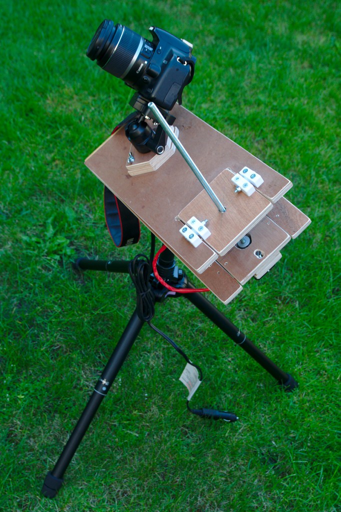
Mount in closed position
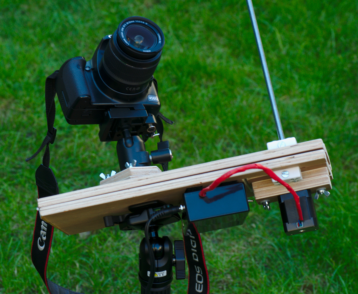
To begin with consider a picture of the complete barn door mount in the initial closed position. This shows how it is attached to the tripod below the mount and how the camera connects above the mount. The power supply cable to the electronic control circuit box can also be seen
Tripod head mounting
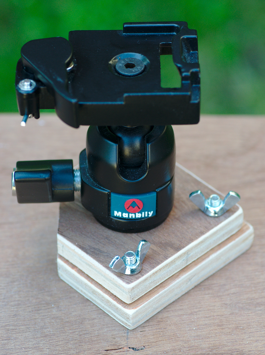
In the construction diagrams it was explained that the tripod head could not be attached directly to the upper panel of the mount. The adjustment handle for the tripod head needs to be able to rotate through 360 degrees. It was sufficient to place two small panels of wood beneath the tripod head to raise it up. The primary bolt going into the base of the tripod head is thus concealed inside the lower panel.
Tripod captive nut
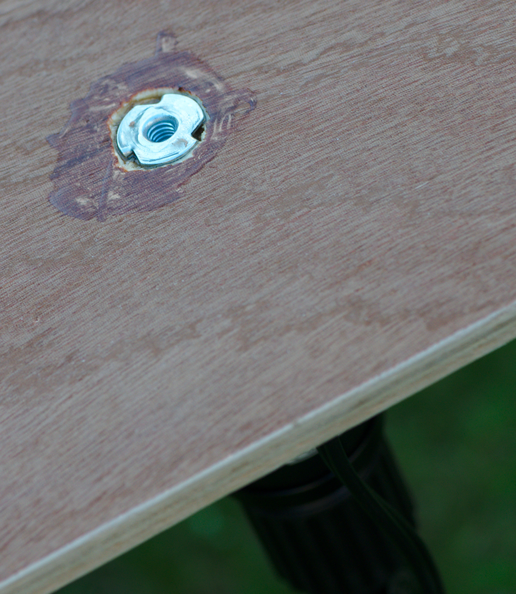
In the lower panel of the mount there is a captive nut embedded in the wood. A captive nut has three spikes which stick into the wood and prevent it from turning or otherwise coming loose. It is embedded in the panel from above so that the force exerted by the coupling to the tripod is actually pulling the nut into the wood. A good amount of epoxy resin ensures there’s absolutely no chance of this nut coming loose, which is good because it takes the entire load of the mount and camera.
Panel hinges
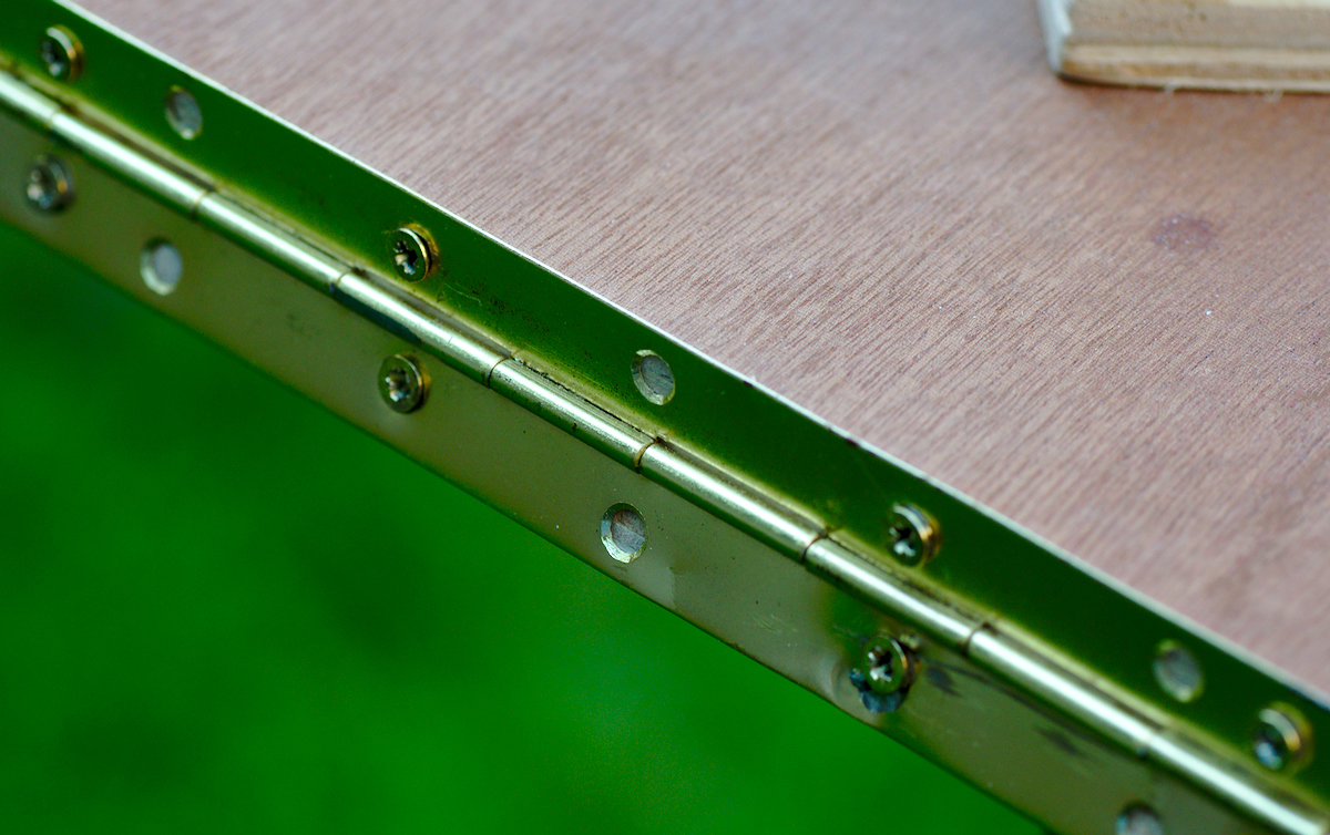
The two primary panels of the mount are connected with a piece of continuous “piano” hinge. Using a single continuous hinge rather than a couple of separate hinges avoids the problem of having to accurately align the two separate hinges.
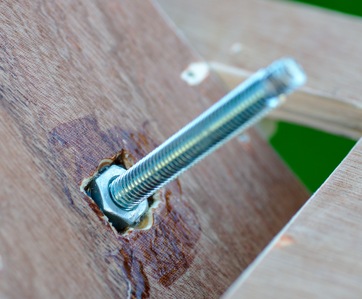
Threaded rod nut
The threaded rod passes through the pivoting part of the top panel. A small nut is recessed into this top panel and held in place with some epoxy resin. Care had to be taken to not get any epoxy on the thread of the embedded nut as that would have totally ruined the ability of the threaded rod to smoothly screw into it
Motor shaft flexible coupling
The pivoting part of the bottom panel has the motor attached. To enable the mount to be completely closed, the motor shaft and flexible coupling had to be recessed. This picture shows the flexible coupling attached to the motor shaft. The end of the threaded rod was squared off so that it can just slot into the coupling whereupon it is held by the tiny screws in the coupling. This makes it easy to remove the threaded rod when the mount is not in use.

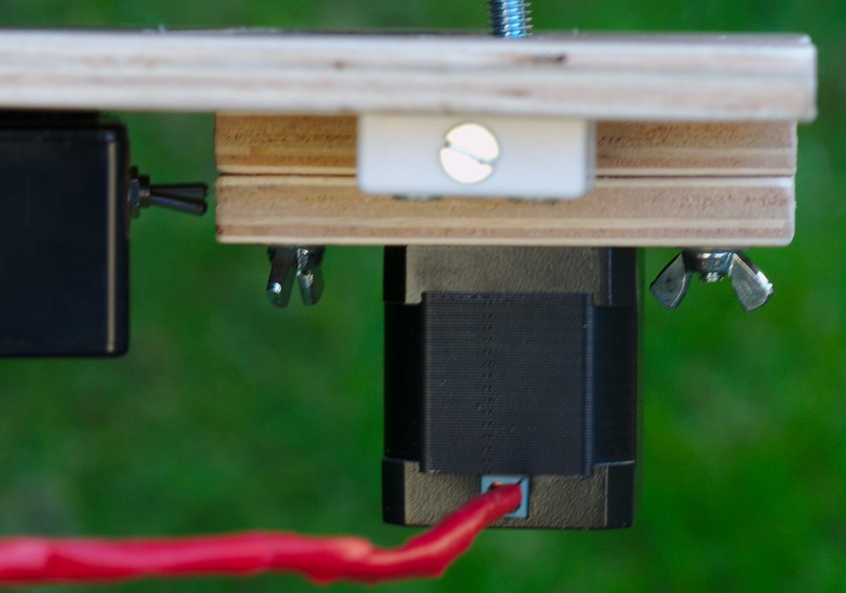
Motor mounting
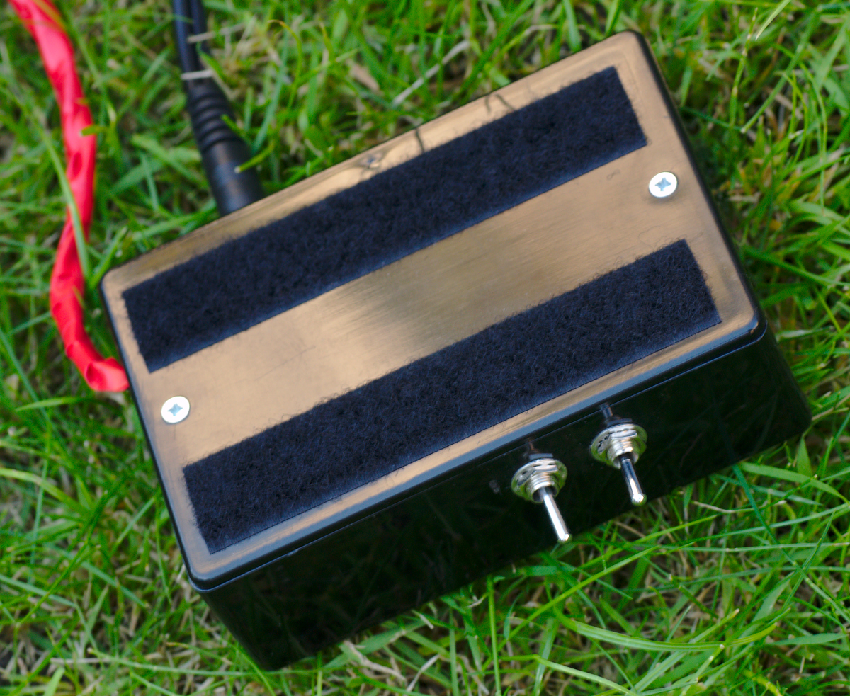
As mentioned earlier, to allow the mount to be completely closed the motor shaft needs to be recessed slightly. Thus two small panels are added to the pivoting panel, attached with short bolts and thumbscrews. The holes through which the bolts pass are rectangular so that they panels can be adjusted horizontally to ensure the motor shaft can be accurately aligned with the pivot hinges. Also seen on the left is the edge of the electronic circuit box with two small switches sticking out. Through a bit of poor planning there was barely sufficient clearance for the switches with the box mounted in this location.
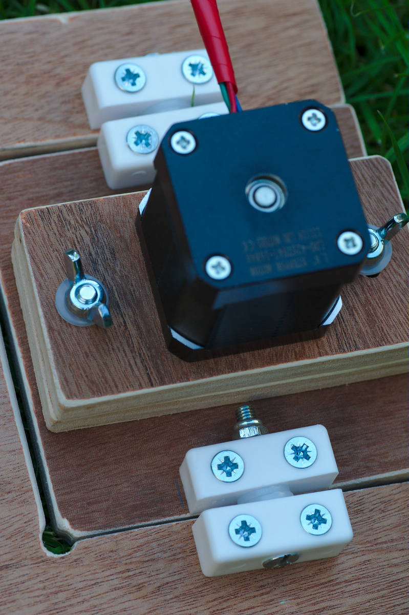
Pivot panel hinge blocks
The movable panels to which the motor and threaded rod are attached need to pivot smoothly as the mount opens. After a prolonged period of indecision the final approach was to make use of some simple plastic furniture fixing blocks. These are attached to both panels and then connected with a small bolt. Two plastics washers keep them separated to the requisite degree and ensure they can move with minimal friction.

Pivoting motor panel
A further view of the pivoting motor panel from below
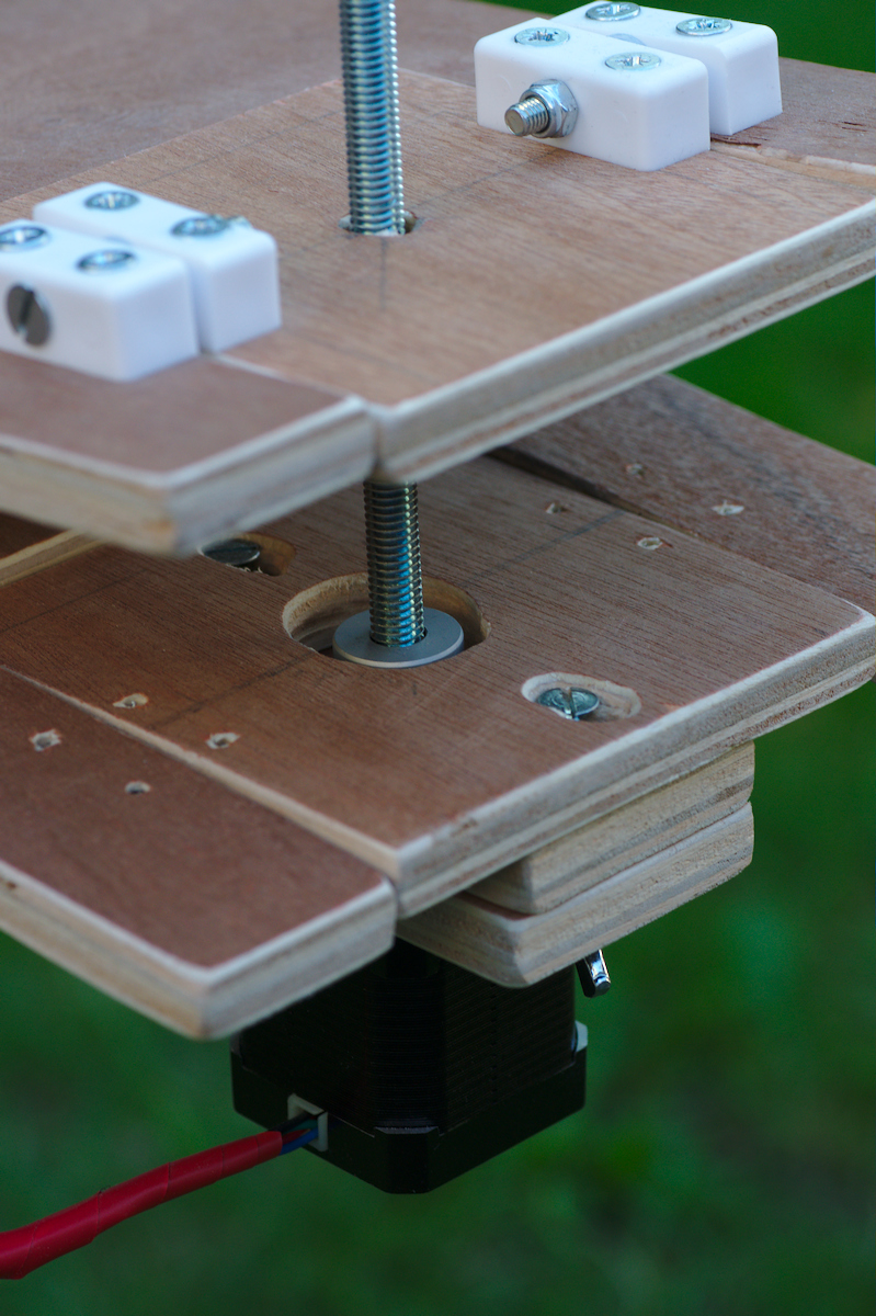
Threaded rod and motor
As the two primary panels open the two pivoting panels should remain parallel to each other as seen in this image. If they don’t remain parallel this indicates that the hinges and / or threaded rod were not correctly aligned with each other.
Electronic control box
The electronic control box had two strips of velcro attached to its lid, which are used to stick it to the mount, a simple but reasonably effective attachment.
Mount from below
Viewed from below it is possible to see the tripod plate attached to the mount, the other velcro strips to which the control box is stuck and finally the pivoting motor panel

Mount in open position
Finally to remind ourselves what the complete mount looks like, consider the mount in a partially open position, as it would be after tracking for 30 minutes or so.
 Thoughts on the construction & design

The more observant readers may have noticed something missing on the mount, specifically a means of aligning it with Polaris. Some people suggest it is possible to align by just visually sighting along the continuous hinge. It only takes one attempt to determine that this is a really unsatisfactory approach. An alternative idea is to attach a green laser pointer to the mount, aligned parallel with the hinge. This would certainly make it easier to visually align with Polaris but unfortunately living near the flight path into Heathrow airport means use of laser pointers is a pretty bad idea in general. Probably the better idea is to get a small gun sight or a red dot finder or some small finder scope. Thus far though I’ve not decided on which solution to go for. Since a big motivation for building a barn door is to keep the costs low, this needs to be taken into account when choosing an alignment method, lest it double the price of the parts !
As mentioned earlier, a mistake was made in positioning the captive nut used to attach the mount to the tripod, which left insufficient clearance for mounting the electronics control box. Also the positioning of the switches, power socket & USB socket on the electronics box was really poorly chosen. They should have all been positioned on the short edges of the box, rather than on the long edges.
The coupling of the motor shaft to the threaded rod was not entirely satisfactory. A flexible coupling seemed like a good idea to avoid undue stress on the apparatus, but in the event there is actually too much flexing in the coupling which means that the pivoting panels don’t always stay parallel to each other as the threaded rod rotates. A rigid coupling of the threaded rod & motor shaft would probably have worked better. As a hack I might attempt to bind the flexible coupling in tape and/or glue to make it less flexible and reduce the wobble in the panels.
Overall the project took a bit longer to complete than anticipated and cost more than is really necessary to build an effective barn door, due to cost of the electronics. As a person commenting on an earlier part in this series says, using a threaded rod would provide a much simpler design which could be powered with a simple fixed rate motor and no need for the arduino. A large part of the motivation (and fun) of the whole enterprise though was to actually learn about arduino programming and electrical circuit construction. In this respect it has been a very successful project, even if overkill for a barndoor. The arduino also has the capability to be used to correct for construction errors, meaning it was not necessary to be too accurate with the measuring of the mount, and could be extended in future to also automate triggering of the camera shutter for specific time periods.
Unfortunately a combination of other life commitments, awful weather in the first part of the year and heavy light pollution mean that I’ve not had much opportunity to actually use the completed barn door mount yet. It has just had a few simple tests to check that the electronics and mechanics were working correctly. In these tests I determined that the tripod I have for holding the mount is not very well suited to the job, as it has a head which freely moves in any of the 3 axis of rotation at once. This makes it a really pain to align the mount with Polaris. What is needed is a tripod which allows each of the 3 axis to be adjusted completely independently. As a result of this and lack of a good polar alignment method, it hasn’t been possible to get any decent pictures of the night sky using the mount yet, hence why none are shown here. Hopefully I’ll be able to put this right over the coming months at which point I’ll post them to demonstrate the mount capabilities.
Thanks for posts 4 and 5 – very useful.
Hi,
Thanks for sharing the construction of your tracking mount. I also want to build one and am not able to find the exact motor in the USA e-bay. I am wondering if besides the 1.8 degree step resolution there is anything else that I need to be looking for. I am looking at the hybrids as it seems they offer more smooth operation.
By the way, where can I see some pictures you have taken with this mount.
Thanks again.
Farzad
You don’t need the same exact motor I used – just search ebay for “stepper motor 1.8” and you’ll see plenty of relevant results from suppliers in the US.
As mentioned in this post, I’ve not had a chance to really try out the mount for real yet, so don’t have photos to share
One other question: how did you couple the motor shaft and the threaded rod?
Thanks
I used a 5x8mm flexible coupling – just search eBay for “5x8mm flexible coupling” and you’ll find plenty of hits. In my case 5mm was the motor shaft diameter, while 8mm was the threaded rod diameter. If you have a different sized threaded rod or motor shaft just look for a different sized coupling – they come in many combinations of sizes.
Hi! Great build thread. I’m attempting to build my own and borrowing your hinged motor/threaded rod idea to eliminate tracking/tangent errors. I want to get done by the end of Nov since I’m going camping in a dark sky area for Thanksgiving – this would be awesome if I can get it done. I’m right now stuck at selecting a motor-driver combo. There are so many choices, it’s mind-boggling! My main motivations are to eliminate manual cranking and use my spare Uno that’s been lying around. Is it critical as to where the camera gets mounted on the top arm; does that distance from the motor’s center-line to the tripod head matter?
The location of the camera on the top arm doesn’t matter from the point of view of the tracking. Just bear in mind that when the mount is polar aligned the camera will be exerting a non-negligible force on the main hinge between the two arms. For that reason I felt it better to position the camera closer to the hinge. The only really important distance is between the hinge and motor threaded rod
Thanks for the reply! Yup, I realized soon after commenting that the location of the camera doesn’t really matter but the apparent distance from the pole star (hinge) to the motor center-line that matters for the moment arm. Anyway, I’m pretty much mimicking your circuit except that I’m using this motor – http://www.canakit.com/Media/STM100.pdf. However, the motor doesn’t turn at all. I’m running it using your test code and the phases & polarity are matched up exactly as the datasheet. The serial monitor for the Arduino shows the code is running perfectly and the EasyDriver lights up with the red LED as it should (+5V). I’m using a 12V supply from my telescope. Any ideas?
The motor specs all look reasonable, so I’ve just got to imagine it is a wiring mistake. I’m not an expert in stepper motors, but IIUC if a step motor doesn’t turn its usually a sign that the wires for one or both of the phases are the wrong way around. So I can just suggest double checking all the wires again
Arghh! :) I’ve now replaced both the EasyDriver & motor in an effort to rule out their manufacturing defects but I still get nothing. While turning the potentiometer on the ED, the motor twitches at certain points but it doesn’t continue to turn. I’ve checked & confirmed that the Uno is pulsing the right pins and it’s good. Therefore, I’m thinking there are power issues between the motor and the driver. Unfortunately, electronics is not my strong point and I feel like a fish out of water! :)
boilerdam, did you ever figure out what was wrong?
Something that tripped me up for a while – in the test code in part 1, the step and direction pins are swapped. Step pin is 8, it needs to be 9 (has to be a pwm pin, the schematic is correct).
Daniel, there is a bug on the test code in step 1. :)
This looks like a very well thought out design. Well done. It is nearly a year since part 5 of the project was posted. Have you had the opportunity to take any images and put them online?
Well, I’ve not tried using the barndoor nearly as much as I would have liked to. In the times I’ve taken it out I’ve had trouble getting sufficiently good polar alignment, as my South London skies have terrible light pollution when looking for Polaris :-( This has really limited my ability to test it out for real. So, thus far, the results I’ve had are disappointing but I can’t tell if its a problem with the barndoor itself or not. I’m still reasonably confident the design and tracking code works, as I’ve measured the rate of opening and compared it to what is required and it matches that. I really just need to get some dark sky testing, but no idea when that’ll be.
Good place to go as your in South London is Box Hill looking South lot less light polution
Have you considered some kind of manual speed up and slowdown correction for mechanical periodic errors and such? I was thinking of putting a small spotting scope on it, and then hit a button that would speed it up or slow it down if it drifted too far. I would be cool to make it so that it responds to audio so that you don’t introduce errors into it by touching anything. Say “faster” and then “resume”, or “slower”.
Another thing to do would be to add two limit switches, one for rewind and one for stopping at the end.
I like this. Thanks a lot, I’ve been toying with the idea of a curved threaded rod with a gear follower on it, that would negate the changing rates, but it’s hard to implement in reality. I’m leaning toward this now.
-Bill Wheaton
Decatur, GA, USA
I’d not really considered the idea of manual speed up/down. I figured that if it was found to be drifting significantly I would just tweak the software to accommodate it. As for limits, the software contains a built-in limit so it will stop before it opens too far. If you flickr the mode switch from “tracking” to “fast”, and the direction switch to reverse, it will run at high speed until it returns to the closed position and then stop. It does this by remembering how many revolutions it has turned since being switched on, and just goes until it cancels that out.
As for the curved rod, if you can get an accurate curve on the rod, I think that would likely give a better overall mechanical design – the pivoting plates to hold the straight rod are the main weakness of this design I did. I did the design I did though because I don’t really have the tools available to do a good bend on the rod and am better at writing software
One thing I’m concerned about is ringing (assuming you’re doing full stepping) Have you thought about putting a dampening weight on the rod? Or are you doing micro-stepping? Or both?
Also, what is the average step rate, approximately while running? I’m trying to get a feel for how fast it is stepping.
Yes, the motor is micro-stepping at 8-microsteps. When the motor is in tracking mode the rate of rotation is so slow that you would barely notice it moving, so there’s no risk of “ringing” there. When it is in high speed mode for the purpose of rewind there is noticeable oscillation but that’s not a big deal since you’re not taking photos in high speed mode. I can’t remember the exact rate of rotation when tracking, but it was on the order of one complete rotation per minute, which equates to about 2400 microsteps per minute
Great blog and design, finished building mine a while back, but decided to do a few mods, after trying it out a couple of times so I thought i would let you know.
As I’m only going to use the barn door in the UK, the alignment to Polaris is always going to be roughly the same, so have modified the camera mount by cutting a wooden wedge and mounting the tripod head plate onto the top of the wedge, as when the barn door is aligned the tripod head mount is then level and has much more movement.
Ive done the same to the mounting point to the tripod, fitting a wooden wedge to the base, meaning the weight of the barn door plus camera is more central over the tripod and less likely to topple over.
I’ve got some pics i can send to you if you want.
Thank you very much for your time.
When trying to compile I get the following error message:
barndoor:81: error: ‘state_sidereal_enter’ was not declared in this scope
static State stateSidereal = State(state_sidereal_enter, state_sidereal_update, state_sidereal_exit);
Any ideas?
Thanks again
The newer versions of Arduino force functions to be declared before use. I’ve pushed a change to gitlab which moves the FSM variables to hopefully fix these error messages.
Hi Daniel, first I would like to say Thanks for this blog. A few months ago when I was searching the inernet for suitable instructions to build my own barndoor, I found this and I thought this is by far the most modern, complete set of instructions and background information. Great stuff. I completed my project more or less according to your info (100% on the software and electronics part and few rounds of improvements on the hardware side). The major alteration was to invest a few hours into building my own hinge as the piano hinge was found to be too sloppy. It created periodic artefacts. The next step was to improve the polar alignment as the tracking accurancy was not holding beyond 1 min and this could be tracked to misaligment with the pole. So a cheap scope was added, containing a small circular wire indicating the 0.75 deg distance of the pole from Polaris. Now I can track easily for 2 min which is the limit anyway for the light polluted area where I live.
As prove that the whole setup works perfectly and smoothly I have uploaded a few images of my tracker and recent images of Messier objects which I took with our tracker. If yoo or someone is interested those images can be found on my astro Flickr account under https://www.flickr.com/photos/142968846@N07/.
Thanks again for the inspiration.
Bye,
Volker
Nice to hear that it is working out for you – the modifications you made look nice indeed. I too have since replaced the piano hinge with something more substantial and agree that a better polar alignment scope is needed to get good accuracy. Great pics on your flickr account too !
Thanks for the writeup, you mentioned that you have made some upgrades. Do you have any pictures? I am giving this project a shot, I am adding a couple of extra sensors. I am adding a gps to get the lattitude, a gyrocompass for finding North and the azimuth from the lattitude to help with polar alignment.
Thanks for doing this in such detail Daniel. This project has been a great learning experience for me. I enjoyed building this project. Something I would like to add to mine in the future is a red LED to indicate when the rotating and/or flash when it is stationary.
Thanks for the writeup, it has inspired me to build my own.
Like some of the other commenter’s, I have made a few modifications to your design. First I will be mounting the mount on a horizontal board, with wooden triangles cut to hold the barn door at the appropriate angle for my latitude. A bubble level will be used to level the horizontal board. In addition, a compass can be used to find North, and then turning the mount to correct for magnetic North.
I am using the 5 volt regulator on the EasyDriver to provide power to my Arduino. Since I intend to run from battery power, I have also added a connection from the Arduino to the EasyDriver to put the EasyDriver to sleep, when the motor is stopped. Otherwise, even at rest, the motor is holding still at full power.
I have found one little potential source of tracking error in your code. In the writeup, you state that sidereal time is: “23 hours, 56 minutes, 4.0916 seconds, or more simply 86164.0419 seconds. ” It should be 86164.0916 seconds, not 86164.0419 seconds. Probably not significant, but every little bit of accuracy is one less source of error.
One of the commenter’s was talking about using voice control, to avoid physically touching the setup. Instead of voice control, I would suggest adding IR remote control. A cheap IR receiver sensor can be used, along with a generic IR remote control. Any number of commands could be added, including replacing the direction and speed control switches with IR commands. I’m also considering adding an intervalometer function, so that I can take stacked photos
Hello!
This looks like a great build that you’ve made, and thanks so much for all the info and time you’ve put in to the blog!
I’m curious about vibrations, because I’ve just started experimenting with stepper motors and the ones I’ve used vibrate when I run them with easy driver/arduino. Not violently, but enough that I fear that it might just affect the barn door tracker. Have you experienced this, and if so, do you have any ideas about what to do about it?
Regards,
Jonathan
Hi! What amps did yoz set on EasyDriver by the potentiometer?
It can be set up between 150-750mA power for pulses.
What was your setup?
Mine nema17 motor needs 1.3Amps in the data sheet, but if I run at 750mA so max of easydriver it is very noisy and makes erros, with arond 200mA it is better so not know what is the best.
I have a 1:100 gearbox and not using microstepping.