Part 1, part 2, part 3 and part 4 of this series consider the electrical circuit construction, mathematics behind the drive mechanism, the control software code and construction diagrams. At this stage readers are probably wondering if the finished device will ever appear. This final part will answer that question via a short picture gallery.
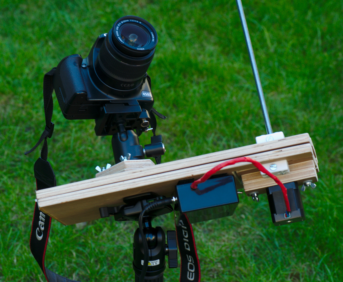
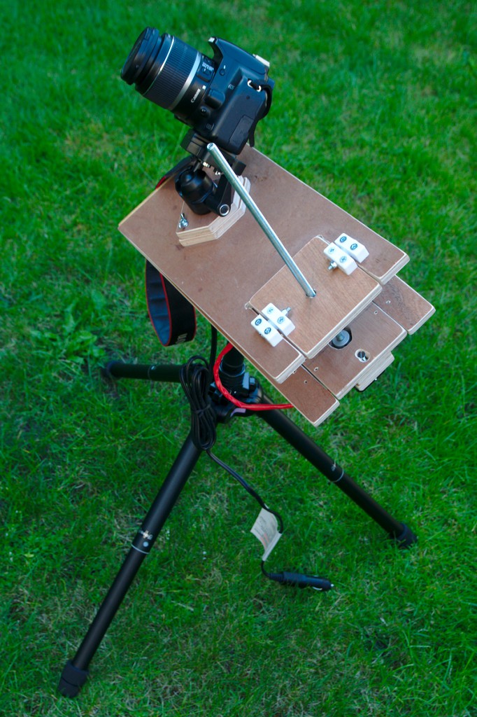
Mount in closed position
To begin with consider a picture of the complete barn door mount in the initial closed position. This shows how it is attached to the tripod below the mount and how the camera connects above the mount. The power supply cable to the electronic control circuit box can also be seen
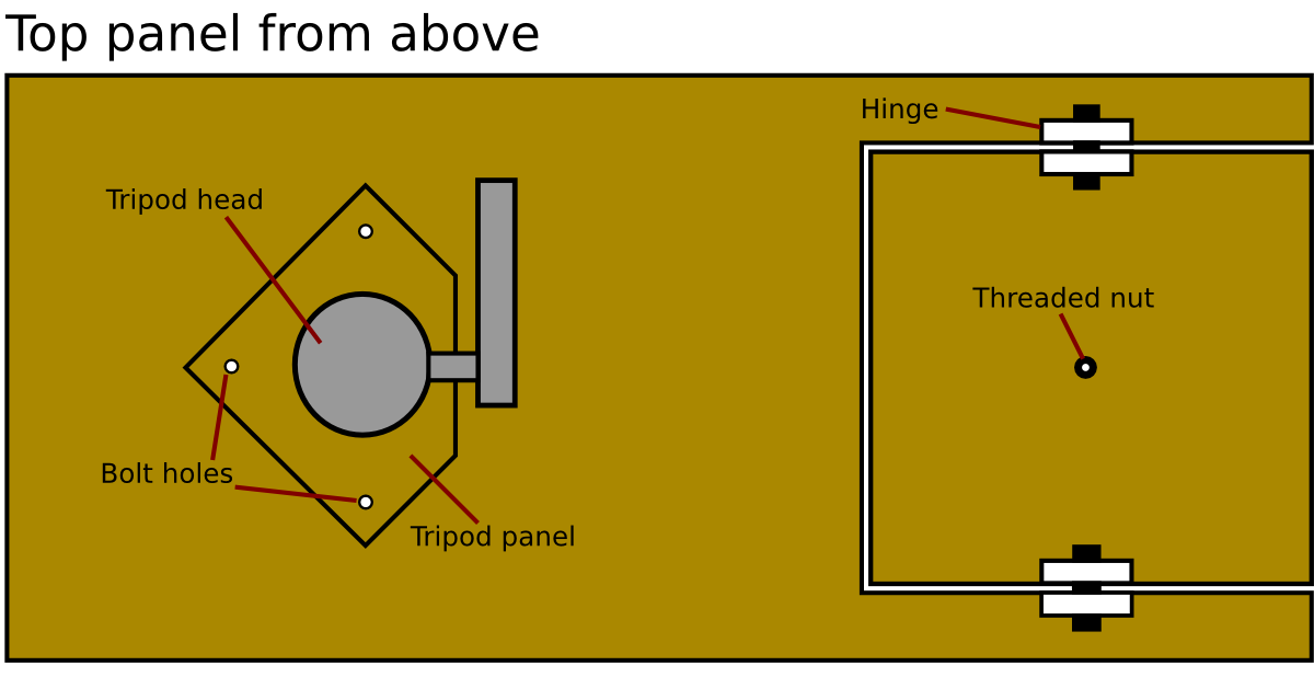
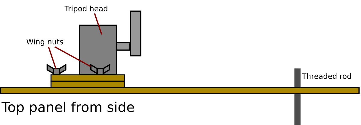
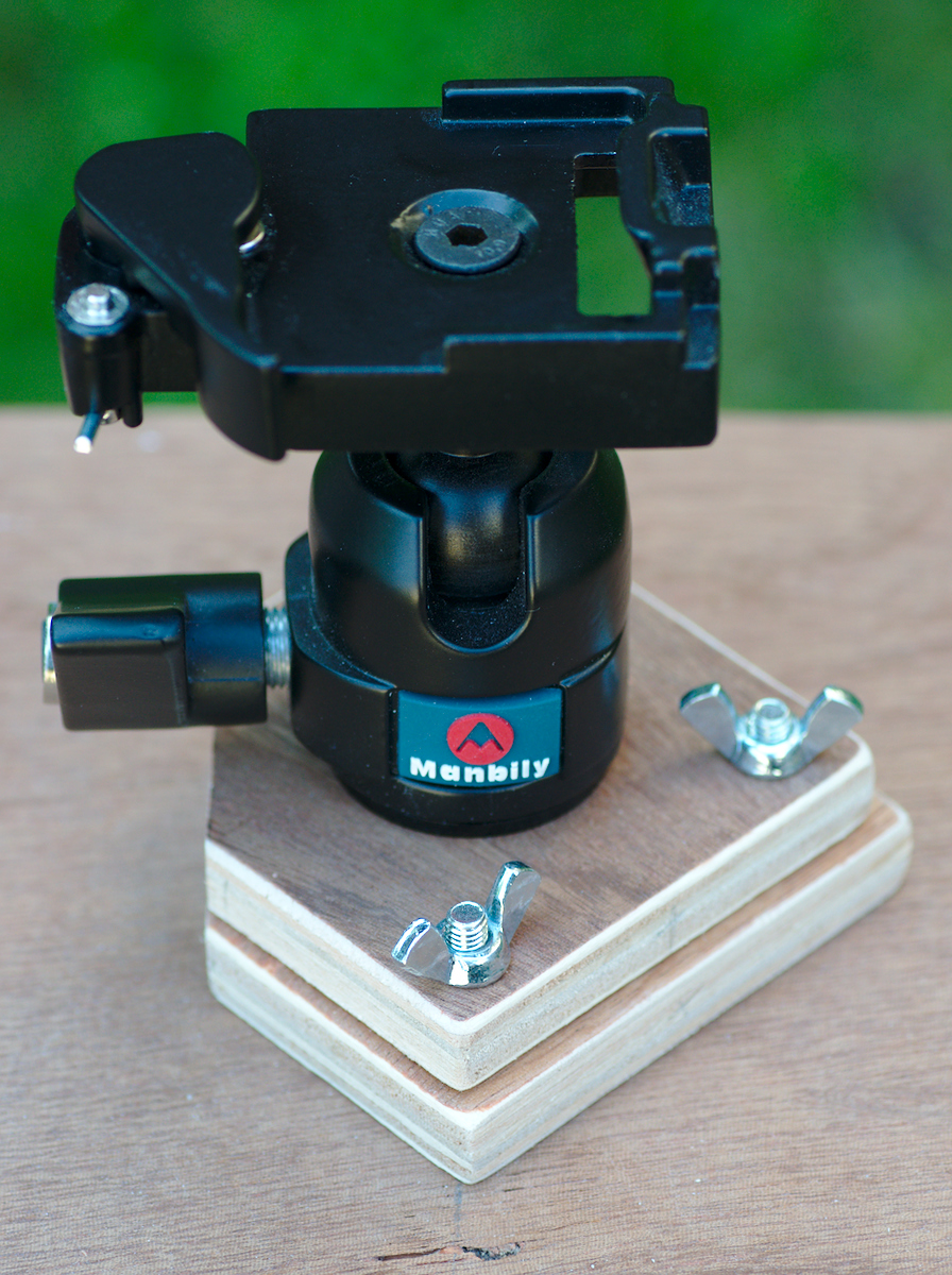
Tripod head mounting
In the construction diagrams it was explained that the tripod head could not be attached directly to the upper panel of the mount. The adjustment handle for the tripod head needs to be able to rotate through 360 degrees. It was sufficient to place two small panels of wood beneath the tripod head to raise it up. The primary bolt going into the base of the tripod head is thus concealed inside the lower panel.
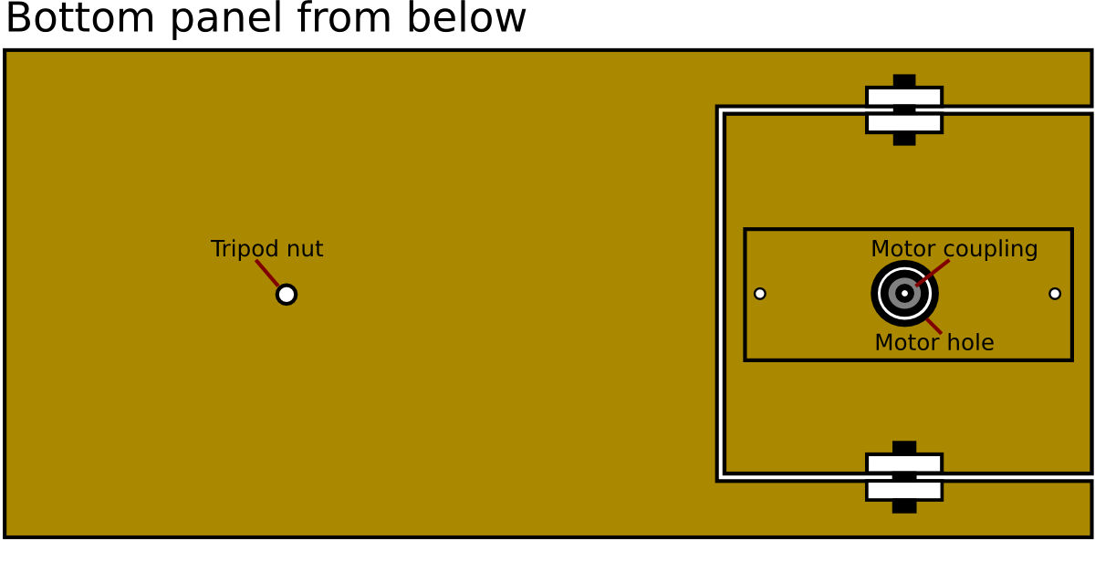
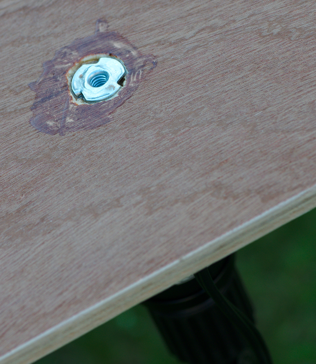
Tripod captive nut
In the lower panel of the mount there is a captive nut embedded in the wood. A captive nut has three spikes which stick into the wood and prevent it from turning or otherwise coming loose. It is embedded in the panel from above so that the force exerted by the coupling to the tripod is actually pulling the nut into the wood. A good amount of epoxy resin ensures there’s absolutely no chance of this nut coming loose, which is good because it takes the entire load of the mount and camera.
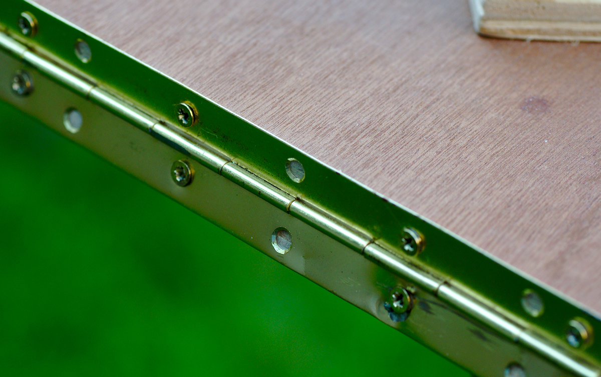
Panel hinges
The two primary panels of the mount are connected with a piece of continuous “piano” hinge. Using a single continuous hinge rather than a couple of separate hinges avoids the problem of having to accurately align the two separate hinges.
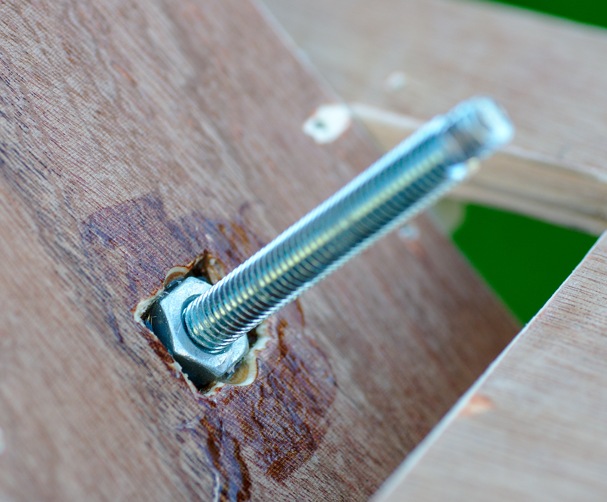
Threaded rod nut
The threaded rod passes through the pivoting part of the top panel. A small nut is recessed into this top panel and held in place with some epoxy resin. Care had to be taken to not get any epoxy on the thread of the embedded nut as that would have totally ruined the ability of the threaded rod to smoothly screw into it
Motor shaft flexible coupling
The pivoting part of the bottom panel has the motor attached. To enable the mount to be completely closed, the motor shaft and flexible coupling had to be recessed. This picture shows the flexible coupling attached to the motor shaft. The end of the threaded rod was squared off so that it can just slot into the coupling whereupon it is held by the tiny screws in the coupling. This makes it easy to remove the threaded rod when the mount is not in use.

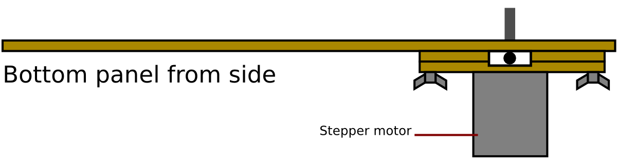
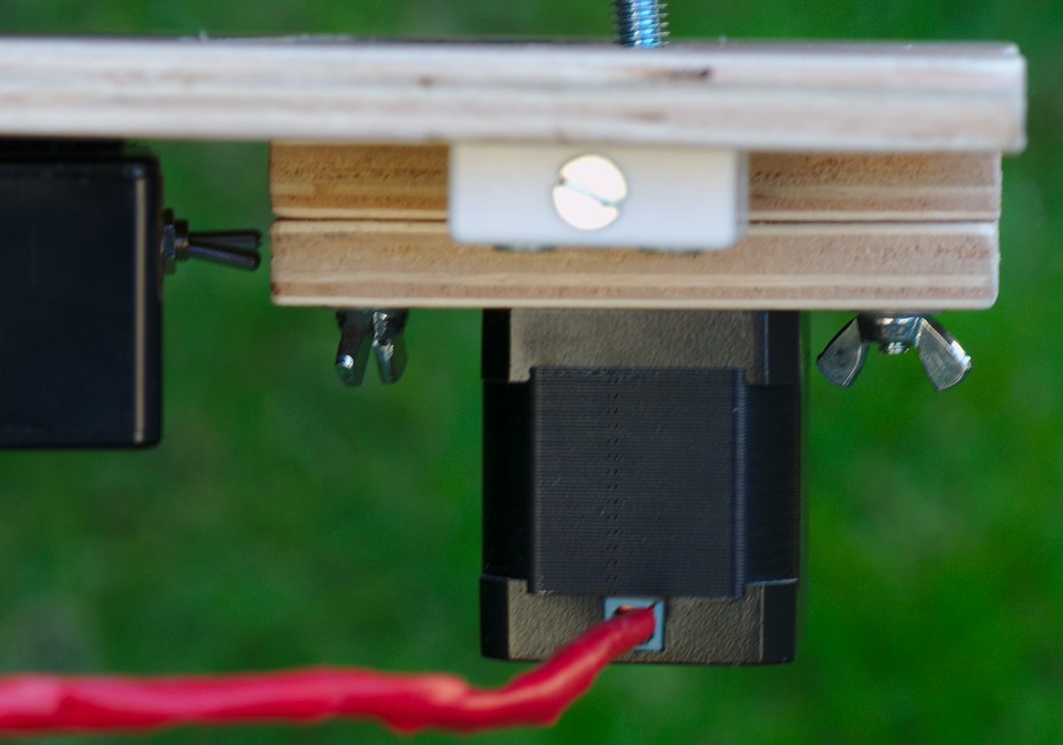
Motor mounting
As mentioned earlier, to allow the mount to be completely closed the motor shaft needs to be recessed slightly. Thus two small panels are added to the pivoting panel, attached with short bolts and thumbscrews. The holes through which the bolts pass are rectangular so that they panels can be adjusted horizontally to ensure the motor shaft can be accurately aligned with the pivot hinges. Also seen on the left is the edge of the electronic circuit box with two small switches sticking out. Through a bit of poor planning there was barely sufficient clearance for the switches with the box mounted in this location.
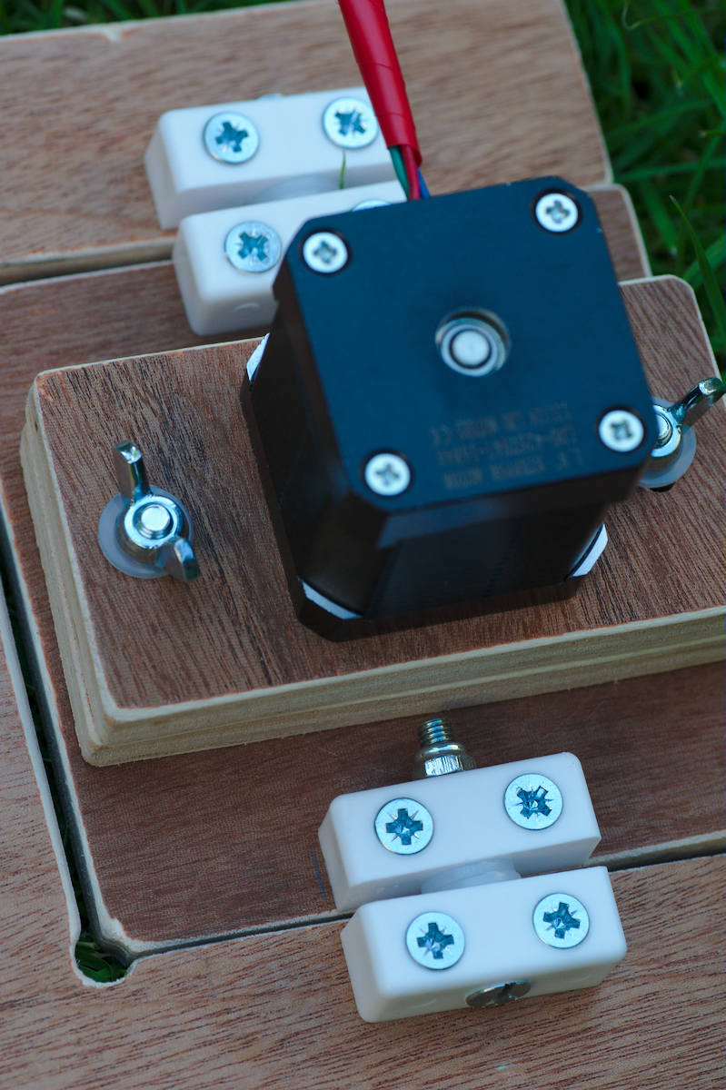
Pivot panel hinge blocks
The movable panels to which the motor and threaded rod are attached need to pivot smoothly as the mount opens. After a prolonged period of indecision the final approach was to make use of some simple plastic furniture fixing blocks. These are attached to both panels and then connected with a small bolt. Two plastics washers keep them separated to the requisite degree and ensure they can move with minimal friction.

Pivoting motor panel
A further view of the pivoting motor panel from below
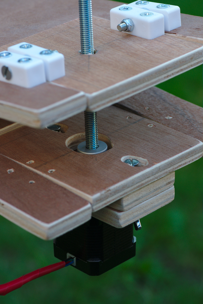
Threaded rod and motor
As the two primary panels open the two pivoting panels should remain parallel to each other as seen in this image. If they don’t remain parallel this indicates that the hinges and / or threaded rod were not correctly aligned with each other.
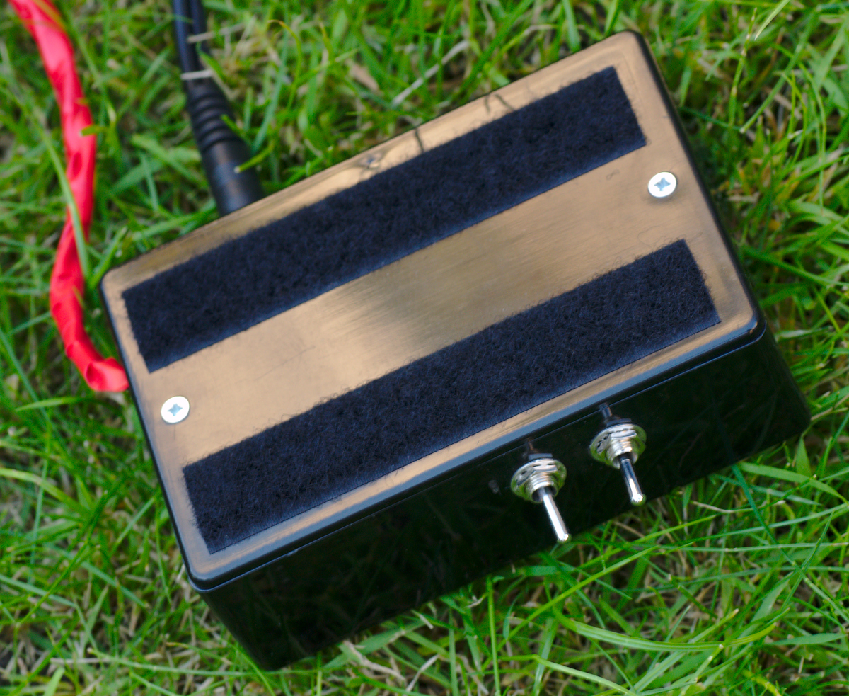
Electronic control box
The electronic control box had two strips of velcro attached to its lid, which are used to stick it to the mount, a simple but reasonably effective attachment.
Mount from below
Viewed from below it is possible to see the tripod plate attached to the mount, the other velcro strips to which the control box is stuck and finally the pivoting motor panel

Mount in open position
Finally to remind ourselves what the complete mount looks like, consider the mount in a partially open position, as it would be after tracking for 30 minutes or so.
 Thoughts on the construction & design

The more observant readers may have noticed something missing on the mount, specifically a means of aligning it with Polaris. Some people suggest it is possible to align by just visually sighting along the continuous hinge. It only takes one attempt to determine that this is a really unsatisfactory approach. An alternative idea is to attach a green laser pointer to the mount, aligned parallel with the hinge. This would certainly make it easier to visually align with Polaris but unfortunately living near the flight path into Heathrow airport means use of laser pointers is a pretty bad idea in general. Probably the better idea is to get a small gun sight or a red dot finder or some small finder scope. Thus far though I’ve not decided on which solution to go for. Since a big motivation for building a barn door is to keep the costs low, this needs to be taken into account when choosing an alignment method, lest it double the price of the parts !
As mentioned earlier, a mistake was made in positioning the captive nut used to attach the mount to the tripod, which left insufficient clearance for mounting the electronics control box. Also the positioning of the switches, power socket & USB socket on the electronics box was really poorly chosen. They should have all been positioned on the short edges of the box, rather than on the long edges.
The coupling of the motor shaft to the threaded rod was not entirely satisfactory. A flexible coupling seemed like a good idea to avoid undue stress on the apparatus, but in the event there is actually too much flexing in the coupling which means that the pivoting panels don’t always stay parallel to each other as the threaded rod rotates. A rigid coupling of the threaded rod & motor shaft would probably have worked better. As a hack I might attempt to bind the flexible coupling in tape and/or glue to make it less flexible and reduce the wobble in the panels.
Overall the project took a bit longer to complete than anticipated and cost more than is really necessary to build an effective barn door, due to cost of the electronics. As a person commenting on an earlier part in this series says, using a threaded rod would provide a much simpler design which could be powered with a simple fixed rate motor and no need for the arduino. A large part of the motivation (and fun) of the whole enterprise though was to actually learn about arduino programming and electrical circuit construction. In this respect it has been a very successful project, even if overkill for a barndoor. The arduino also has the capability to be used to correct for construction errors, meaning it was not necessary to be too accurate with the measuring of the mount, and could be extended in future to also automate triggering of the camera shutter for specific time periods.
Unfortunately a combination of other life commitments, awful weather in the first part of the year and heavy light pollution mean that I’ve not had much opportunity to actually use the completed barn door mount yet. It has just had a few simple tests to check that the electronics and mechanics were working correctly. In these tests I determined that the tripod I have for holding the mount is not very well suited to the job, as it has a head which freely moves in any of the 3 axis of rotation at once. This makes it a really pain to align the mount with Polaris. What is needed is a tripod which allows each of the 3 axis to be adjusted completely independently. As a result of this and lack of a good polar alignment method, it hasn’t been possible to get any decent pictures of the night sky using the mount yet, hence why none are shown here. Hopefully I’ll be able to put this right over the coming months at which point I’ll post them to demonstrate the mount capabilities.