Tag Archives: arduino

Building a barn door mount, part 3: drive control software

Part 1 and part 2 of this series considered the electrical circuit construction and mathematics behind the drive mechanism respectively. There was a short demonstration of arduino code to drive the motor in part 1 but this did not attempt to do any kind of proper rate tracking since it was awaiting the mathematics in part 2. This part of the series of blog postings will thus consider the actual code required to do accurate rate tracking. For the impatient, the full working code is published under the GPL version 3 or later license at gitorious.

EDIT 2015/7/22: With gitorious going away, the code now lives at gitlab

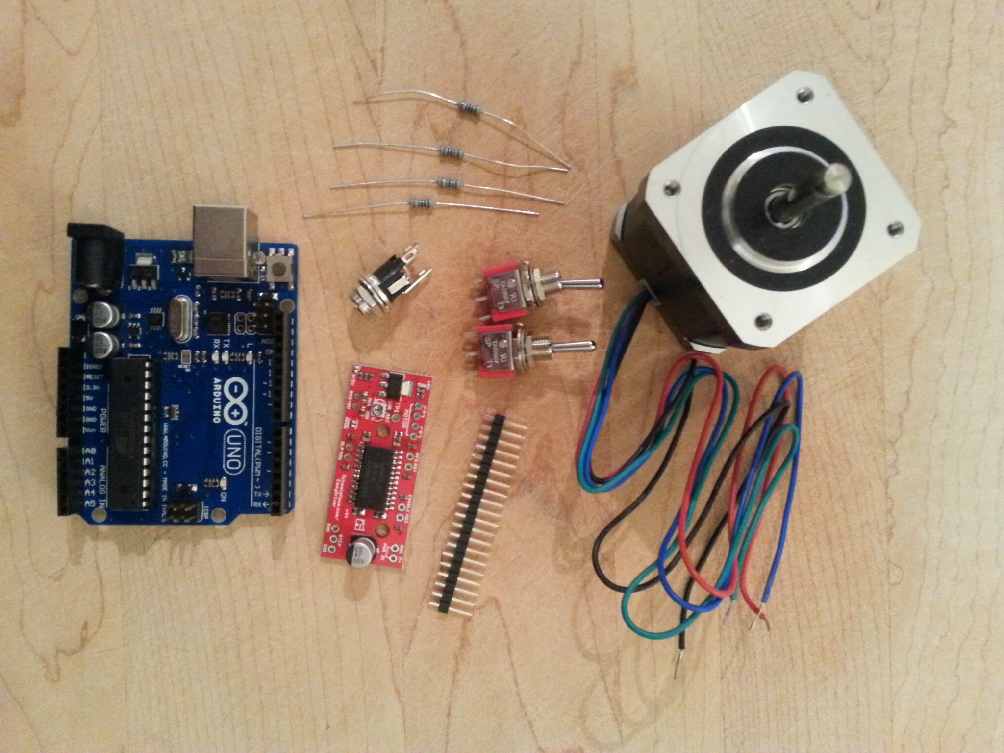
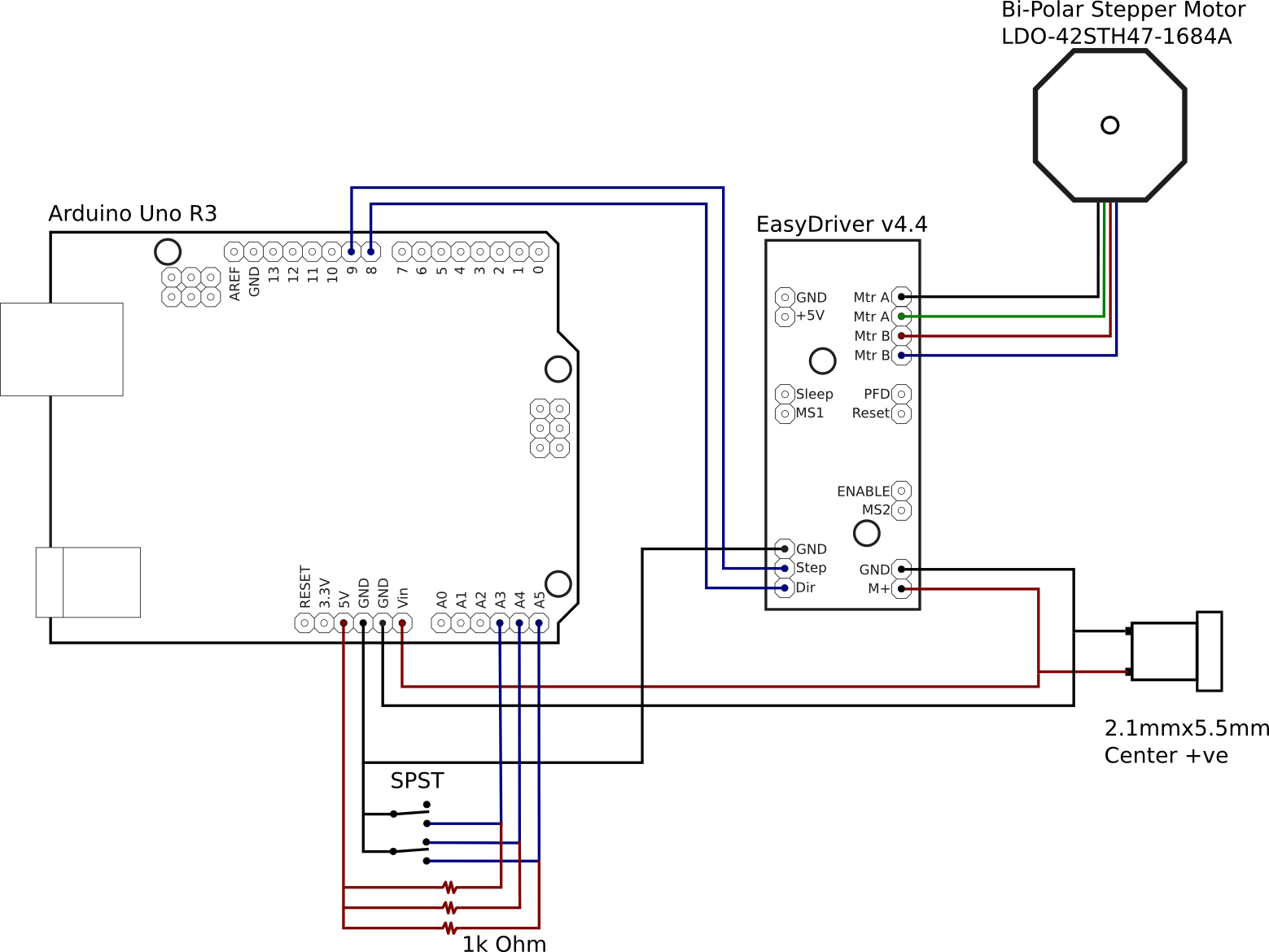
Since the writing of part 1, a slight change was made to the usage of the two switches. The ON/ON switch, connected to analogue pin 3, is to be used to switch direction of rotation between forwards (moving with the earth’s rotation) and backwards (moving against the earth’s rotation). The ON/OFF/ON switch, connected to analogue pins 4 and 5, is to be used to control the mode of operation between automatic tracking, stopped and non-tracked high-speed. The idea of the latter mode is to allow the mount to be more quickly reset back to the starting position. For convenience the code defines constants for the analogue input and digital output pins based on their intended function

static const int pinOutStep = 9; // Arduino digital pin connected to EasyDriver step
static const int pinOutDirection = 8; // Arduino digital pin connected to EasyDriver direction

static const int pinInAutomatic = 4; // Arduino analogue pin connected to automatic mode switch
static const int pinInManual = 5; // Arduino analogue pin connected to manual mode switch
static const int pinInDirection = 3; // Arduino analogue pin connected to direction switch

The core design concept for the code is to have a finite state machine associated with the ON/OFF/ON switch. Rather than implement the finite state machine concept from scratch, it reuses the existing FiniteStateMachine module. Thus in order to compile the sample code, the ZIP file for this module must be downloaded and imported into the arduino project. The same is true of the AccelStepper library used for motor control. Since the switch has three positions, there are three states in the FSM declared as global variables. When declared, each state is provided with three callbacks, one to be invoked when the state is entered, one invoked on each tick while the state is active and one to be invoked when the state is left.

static State stateAuto = State(state_auto_enter, state_auto_update, state_auto_exit);
static State stateManual = State(state_manual_enter, state_manual_update, state_manual_update);
static State stateOff = State(state_off_enter, state_off_update, state_off_exit);
static FSM barndoor = FSM(stateOff);

The state machine is used to control the operation of the stepper motor object

static AccelStepper motor(AccelStepper::DRIVER,
                          pinOutStep,
                          pinOutDirection);

Off state

Starting off with the simplest, stateOff, there is only one callback that needs any logic in it. When entering the ‘off’ state the motor needs to stop turning:

void state_off_enter(void)
{
    motor.stop();
}

Manual running state

Moving on to the next, stateManual, there is again only one callback that needs any logic in it. On each tick while in this state the motor needs to be told to move a fixed amount in the correct direction. The code arbitrarily uses a speed of 5000 – this can obviously be changed to whatever suits. There is one safety measure built-in, when the mount is running in reverse, it should automatically stop when it gets to the completely closed position. Fortunately the AccelStepper library tracks how far the motor turns, so if we assume the mount was set to the completely closed position when first turned on, it is just a matter of checking whether the motor position is zero. As a future enhancement it would also be desirable to add an upper limit on the position because if the mount opens too far it’ll run off the end of the threaded rod and likely flap open causing any attached camera to bash against the tripod legs.

void state_manual_update(void)
{
    if (analogRead(pinInDirection) < 512) {
        motor.setSpeed(5000);
        motor.runSpeed();
    } else {
        if (motor.currentPosition() == 0) {
            motor.stop();
        } else {
            motor.setSpeed(-5000);
            motor.runSpeed();
        }
    }
}

Automatic tracking state

Finally, stateAuto, requires quite a lot more complicated code in its callbacks. At any given point in the time, the speed at which the threaded rod needs to turn is dependent on how far open the mount is. First of all, the code needs to know the position of the mount when automatic tracking started, bearing in mind there could have been arbitrary movement forwards or backwards when in manual mode. As noted before, the code assumes that the mount is in the completely closed position when the electronics are first powered on, which corresponds to motor step count of 0. Thus when entering the automatic tracking state, the position of the mount can be determined from the total number of motor steps. Given the step count, the mathematics from the previous blog post show how to calculate what this corresponds to in tracking time, so a function is defined to do this conversion:

long usteps_to_time(long usteps)
{
    return (long)(asin(usteps /
         (USTEPS_PER_ROTATION * THREADS_PER_CM * 2.0 * BASE_LEN_CM)) *
        SIDE_REAL_SECS / PI);
}

To record the state of the mount at the time automatic tracking begins, three global variables are defined

static long startPositionUSteps;
static long startPositionSecs;
static long startWallClockSecs;

These are initialized by calling another helper function, which also records the current wallclock time reported by the arduino runtime:

void start_tracking(void)
{
    startPositionUSteps = motor.currentPosition();
    startPositionSecs = usteps_to_time(startPositionUSteps);
    startWallClockSecs = millis() / 1000;
}

With the initial position determined, the next job is to determine the speed to move the mount. Since the tangent errors from the mechanical design are quite small, it is not necessary to change the speed on every tick of the arduino code – calculating in 15 seconds blocks is sufficiently accurate. The target for the next 15 second block will be recorded in three more global variables

static long targetWallClockSecs;
static long targetPositionSecs;
static long targetPositionUSteps;

The target wall clock time is just updated in increments of 15, but the target position tracking time is updated based on the delta between the start and target wall clock time. It would be possible to just update the target position tracking time in increments of 15 too, but by using the wallclock time delta, the code automatically accounts for any execution time overhead of the tracking code itself. A subtle difference, but worth doing. Once the target position tracking time is decided, the mathematics from part 1 once again show how to convert it back into a motor step count with a small helper function:

long time_to_usteps(long tsecs)
{
    return (long)(USTEPS_PER_ROTATION *
                  THREADS_PER_CM * 2.0 * BASE_LEN_CM *
                  sin(tsecs * PI / SIDE_REAL_SECS));
}

The three target variables are all updated by yet another helper function

void plan_tracking(void)
{
    targetWallClockSecs = targetWallClockSecs + 15;
    targetPositionSecs = startPositionSecs + (targetWallClockSecs - startWallClockSecs);
    targetPositionUSteps = time_to_usteps(targetPositionSecs);
}

With all these helper functions defined, it is possible to show what action is performed by the callback when entering the automatic tracking state. Specifically it will record the starting position and then plan the first 15 second block of tracking

void state_auto_enter(void)
{
    start_tracking();
    plan_tracking();
}

Now the automatic tracking state is ready to run, it is necessary to actually turn the motor. This is simply a matter of taking the remaining wall clock time for the current 15 second tracking block and the remaining motor steps to achieve the target position and then setting a constant speed on the motor to accomplish that target. The code to do this will recalculate speed on every tick in order to ensure smooth tracking throughout the 15 second block. Once again a helper function is declared to perform this calculation

void apply_tracking(long currentWallClockSecs)
{
    long timeLeft = targetWallClockSecs - currentWallClockSecs;
    long stepsLeft = targetPositionUSteps - motor.currentPosition();
    float stepsPerSec = (float)stepsLeft / (float)timeLeft;

    motor.setSpeed(stepsPerSec);
    motor.runSpeed();

With this final helper function it is possible to implement the callback for running the automatic tracking state. It simply has to apply the current tracking information and occasionally update the tracking target.

void state_auto_update(void)
{
    long currentWallClockSecs = millis() / 1000;

    if (currentWallClockSecs >= targetWallClockSecs) {
        plan_tracking();
    }

    apply_tracking(currentWallClockSecs);
}

Switching FSM states

With the code for operating each state defined, all that remains is to actually switch between the different states. This is done by writing the arduino main loop function to check the input pins which are connected to the operation switch.

void loop(void)
{
    if (analogRead(pinInAutomatic) < 512) {
        barndoor.transitionTo(stateAuto);
    } else if (analogRead(pinInManual) < 512) {
        barndoor.transitionTo(stateManual);
    } else {
        barndoor.transitionTo(stateOff);
    }

    barndoor.update();
}

Hardware specific constants

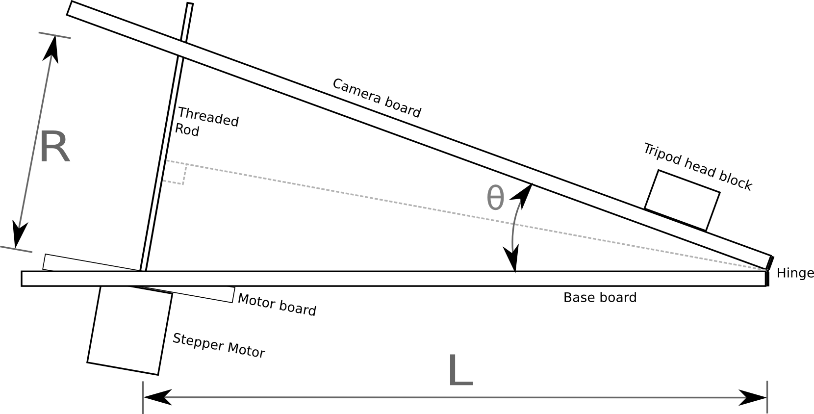
The actual speed of tracking depends on various constants that match the physical construction of the barn door mount. There are only 4 parameters that need to be figured out. The stepper motor will have a number of discrete steps to achieve one complete rotation. The code records this as the number of degrees per step, so if only the step count is known, simply divide that into 360, eg 360/200 == 1.8. The arduino EasyDriver board for controlling the stepper motor is very clever and can actually move the motors in smaller increments than they are officially designed for, currently 8 micro-steps. The next important parameter is the pitch of the threaded rod, which can be determined by just putting a ruler alongside the rod and counting the number of threads in one centimetre. The final piece of information is the distance between the centre of the hinge joining the two pieces of the mount, and the center of the threaded rod. This should be measured once the actual mount is constructed. All these values are defined in constants at the start of the code

static const float STEP_SIZE_DEG = 1.8;
static const float MICRO_STEPS = 8;
static const float THREADS_PER_CM = 8;
static const float BASE_LEN_CM = 30.5;

As mentioned earlier, all the code snippets shown in this blog post are taken from the complete functioning code available under the GPL version 3 or later license at gitorious. With that code compiled and uploaded to the arduino, the electronics are completed. The final part(s) of this blog series will thus focus on the mechanical construction of the mount.

Now read: part 4, construction diagrams.

Building a barn door mount, part 2: calculating mount movements

In part 1 of this series, I described how to construct an Arduino based motor controller. This time around it is time to look at the mathematics behind the movement of the mount. As noted previously, the mount will be driven by a threaded rod. As the motor rotates the rod in a nut attached to the camera board, it generates linear motion, however, the board needs to open up with constant angular motion. For simplicity it is intended to construct a type 1 barndoor mount with an isosceles drive rod, as illustrated in the following diagram

Barndoor mount

In the above diagram the threaded rod has length R between the two boards, forming an angle θ. It can readily be seen from the diagram that the isosceles triangle formed by the two boards and the rod can be split into a pair of identical right angle triangles. Basic trigonometry tells us that the sine of the principal angle in a right angle triangle is equal to the ratio between the opposite and hypotenuse:

formula-1

In our diagram above, the principal angle is θ/2, the length of the opposite is R/2 and the hypotenuse is L. Plugging those symbols into the first formula we get:

formula-2

In order to drive the threaded rod, the value we want to calculate is R, so we need to re-arrange the formula to get R on the left hand side:

formula-3

The Arduino isn’t directly controlling the length of the rod though, rather it is controlling its rotation. The length of the rod is the ratio between the number of rotations and the number of threads per centimetre. This gives us a second formula for R

formula-4

Lets substitute this new formula for R, into the previous formula:

formula-5

A few moments ago we mentioned that the quantity we actually control is the rotation of the rod, so the formula must be re-arranged to get the number of rotations on the right hand side:

formula-6

With this formula, we know how many rotations are needed to achieve a given angle between the boards, but what exactly is the angle we need ? The Earth doesn’t take exactly 24 hours to rotate a full 360 degrees, in fact it is about 23 hours, 56 minutes, 4.0916 seconds. This value is known as the sidereal time or rate. With this information we can now define a formula to derive the value for θ at any given time t, since starting operation of the mount from a closed position:

formula-7

Since θ is the value we need, lets re-arrange that formula to get θ on the right hand side

formula-8

This formula for θ can now be substituted into the earlier formula for calculating the rotations of the rod:

formula-10

The final term can be slightly simplified by removing a factor of 2

formula-11

This formula operates in degrees, but when doing calculations in software it is desirable to measure angles in radians. There is a simple formula for converting from degrees to radians:

formula-9

With this information it is now possible to update the formula for calculating rotations to operate in radians by substituting in the conversion formula:

formula-12

A little while ago it was said that the Arduino is controlling the number of rotations of rod. This isn’t strictly true, it is in fact controlling the number of steps of the motor. A motor will have a certain number of steps it can do in one rotation, which gives a step size in degrees.  The formula for calculating rotations can thus be adapted to calculate the number of steps

formula-13

This is our last formula and it has 4 variables to be filled in with accurate values

  • stepsize: the stepper motor used in the electronics does 200 steps per rotation giving a step size of 1.8. This is a common size for this type of stepper motor. Another typical size is 64 steps per rotation.
  • threads.per.cm: a standard M8 threaded rod will have 10 threads per centimetre, other rods may vary.
  • L: this is the length of the base board between the hinge and the centre of the threaded rod. This has to be precisely measured after construction is complete
  • siderealtime: 23 hours, 56 minutes, 4.0916 seconds, or more simply 86164.0419 seconds

This formula could be executed directly on the Arduino board, but a sine calculation is somewhat heavy for the microcontroller. Realistically the mount isn’t going to be doing exposures of longer than 2-3 hours. It is fairly trivial to thus this formula and calculate the required number of rotations for each minute of each hours and produce a 180 entry table. The Arduino then merely has to keep track of time and do a trivial table lookup to determine the rotation rate. An algorithm for doing this will be the subject of a later blog post.

Now read: part 3, drive control software

Building a barn door mount, part 1: arduino stepper motor control

Serious astronomical imaging requires an equatorial mount for the camera / telescope, which tracks the rotation of the earth for anywhere between 5 minutes and several hours. Commercially available mount options have a starting price of several hundred pounds and range up to thousands. As a result many amateur astro-photographers choose the DIY option, building what’s commonly known as a “barn door mount“. At their simplest, they consist of two parallel planks of wood hinged at one side, with a threaded rod which is manually turned once a minute to gradually open the hinge at a rate which matches the speed of rotation of the Earth.

They are very simple to build, but the pain point should be clear from the end of the previous sentence – you need to control the dimensions such that one rotation of the threaded rod, causes the hinge to open at precisely the right rate. This isn’t as hard as it sounds for short exposures (10-15 minutes) but as the desired exposure time goes up the errors quickly spiral out of control. Some of the error is caused by construction inaccuracies but the bigger part is due to the inherent design decision to produce angular motion (opening hinge) from linear motion (rotating threaded rod). The latter is commonly referred to as the tangent error.

There are various more complicated barn door designs which use 3 pieces of wood to eliminate the tangent errors. Sadly the more complicated designs also increase the mechanical errors due to construction inaccuracies. The easy solution to this problem is to use a programmable microcontroller to drive the mount, allowing arbitrary errors to be corrected in software. When you need a cheap, low power microcontroller, the first option that comes to mind is an Arduino. A little bit of searching on google revealed someone who had built a barn door controlled by an Arduino Uno and a stepper motor. Even better, they provided a sketch of their circuit diagram for wiring it up.

Cost being king, I headed over to eBay to source the big ticket parts, and a maplin store for a few odds & ends I wanted to see in person before purchase. On the list were

Thus the total cost for the electronics was £46.21, a little bit higher than I was originally hoping for. I could have reduced it by going for one of the lower spec stepper motors which are bundled with a driver circuit board. This would have cut approx £12.00 off the cost, but I was not confident it would have sufficient torque for direct drive of the threaded rod, so I went for the sure bet. A pound or two could have been shaved off the cost of switches / power jack too, by sourcing from eBay instead of maplin. IOW it is probably possible to get the parts for about £30-35 if you really find the bargains. Before assembly the parts are laid out

Barndoor electronic parts

In addition to the project parts, you’ll need a few workshop items including a multi-meter, soldering iron, helping hands, wire cutters/strippers and 3A x 12v regulated bench power supply.

After looking at the previously mentioned circuit diagram, I decided to make one slight variation in the use of switches. I discarded the separate power switch, and used all three prongs from one of the switches to toggle between forward/stopped/backward. Thus the aim was to construct the following circuit diagram from the parts:

Barndoor circuit

The Arduino is capable of being powered from the USB port, the on board DC jack, or the VIN pin. While the EasyDriver can take a 5v line from the Arduino board, this is only suitable for driving the electronics, not the stepper motor which needs much higher current than the Arduino is capable of supplying. Thus the decision was made to take a 12V supply from a off-board 2.1mmx5mm DC jack, to the VIN pin on the Arduino and M+ pin on the EasyDriver. The DC jack size was chosen to match that used on the Celestron NexStar telescope mounts, and so was wired center-positive.

The EasyDriver needs a minimum of two control signals, one to trigger a motor step and the other to set the direction of rotation. Thus the Step and Dir pins on the EasyDriver board were connected to the digital pins 8 and 9 on the Arduino. The EasyDriver defaults to 8-point microstepping. If use of full steps were required, the MS1 and MS2 pins could be connected to further digital pins on the Arduino. For the barn door mount though, the rate of rotation is so slow that 8-point microstepping is more than OK.

The two switches are going to be used to provide control parameters to the software running on the Arduino. The ON/OFF/ON switch is going to be used to switch the motion of the motor between clockwise, stopped and anti-clockwise. The ON/ON switch is going to be used to switch between automatic sidereal matched speed control and manual fast speed. For wiring, we effectively have a 1K Ohm resistor between the 5V output pin and an analogue pin. The switch is used to short this link out to ground. Toggling the switch thus toggles the analogue pin high/low.

The final piece of wiring is connecting the stepper motor wires to the EasyDriver. The ordering of the wires is absolutely critical. The stepper motor has two separate coils / phases, and 4 coloured wires coming out of it. Each pair of wires corresponds to one of the phases. The key is determining which wires match which phase and the polarity. Fortunately the stepper motor had a model number on it, allowing the data sheet to be located via google. The data sheet shows that one phase is connected to the black + green wires, while the other phase is connected to the red + blue wires. So the EasyDriver motor pins are wired up in the order black, green, red, blue. Again, this order is absolutely critical to get right – mixing up the polarity between the two coils will result in a motor which won’t turn. Likewise, not matching up wires within a phase will result in a motor which won’t turn. It is also NOT SAFE to use trial and error to test the motor while the EasyDriver is active. Detaching the motor wires while the EasyDriver is active will likely result in a burnt-out EasyDriver. Find the data sheet and get it right first time.

After a hour or two cutting and soldering wires the circuit was complete. To test it requires creation of a simple test program in the Arduino IDE. For this test I’d used the AccelStepper library instead of the Stepper library that is normally used, because the AccelStepper is more flexible to use.

#include <AccelStepper.h>

int debug = 0;

int dgPinStep = 8;
int dgPinDirection = 9;

int anPinForeward = 4;
int anPinBackward = 5;
int anPinSpeed = 3;

AccelStepper stepper(AccelStepper::DRIVER, dgPinStep, dgPinDirection);

void setup() {
  pinMode(anPinForeward,  OUTPUT);
  pinMode(anPinBackward,  OUTPUT);  
  pinMode(anPinSpeed,  OUTPUT);  

  stepper.setMaxSpeed(3000);

  if (debug) {
    Serial.begin(9600);
  }
}

void loop() {
  int valForeward = analogRead(anPinForeward);
  int valBackward = analogRead(anPinBackward);
  int valSpeed = analogRead(anPinSpeed);
  int run = 0;

  if (debug) {
    Serial.print("Foreward: ");
    Serial.print(valForeward);
    Serial.print(" Backward: ");
    Serial.print(valBackward);
    Serial.print(" Speed: ");
    Serial.println(valSpeed);
  }
  if (valForeward < 5) {
    if (valSpeed < 5) {
      stepper.setSpeed(200);
    } else {
      stepper.setSpeed(2000);
    }
    run = 1;
  } else if (valBackward < 5) {
    if (valSpeed < 5) {
      stepper.setSpeed(-200);
    } else {
      stepper.setSpeed(-2000);
    }
    run = 1;
  } else {
    run = 0;
  }

  if (run) {
    stepper.runSpeed();
  } else {
    stepper.stop();
  }
}

After compiling and uploading to the Arduino over USB, the program will start running immediately. If you’re not confident that the switch pins are connected in the right order the “debug” variable can be set to 1, which will let you watch the levels via the IDE’s serial console as the switches are toggled. Just remember to turn off debugging again afterwards because the println calls seriously slow down the program to the point that it is unusable in the real world. The video shows toggling the motion switch between forward/off/backward and the speed switch between slow/fast (sidereal rate is not implemented in the test program)

With everything working, all the remains is to house it in the plastic case. This required drilling a few holes for the switches and DC hack, and carving out a hole with a file for the USB port and carving a channel for the motor wires. With the electronics complete, the next phases are to build the mechanical side of the mount and then do the maths calculations and software programming necessary to track the earth’s rotation accurately. These will follow as separate blog posts in the coming days or weeks.

Now read: part 2, calculating mount movements