In part 1 of this series, I described how to construct an Arduino based motor controller. This time around it is time to look at the mathematics behind the movement of the mount. As noted previously, the mount will be driven by a threaded rod. As the motor rotates the rod in a nut attached to the camera board, it generates linear motion, however, the board needs to open up with constant angular motion. For simplicity it is intended to construct a type 1 barndoor mount with an isosceles drive rod, as illustrated in the following diagram
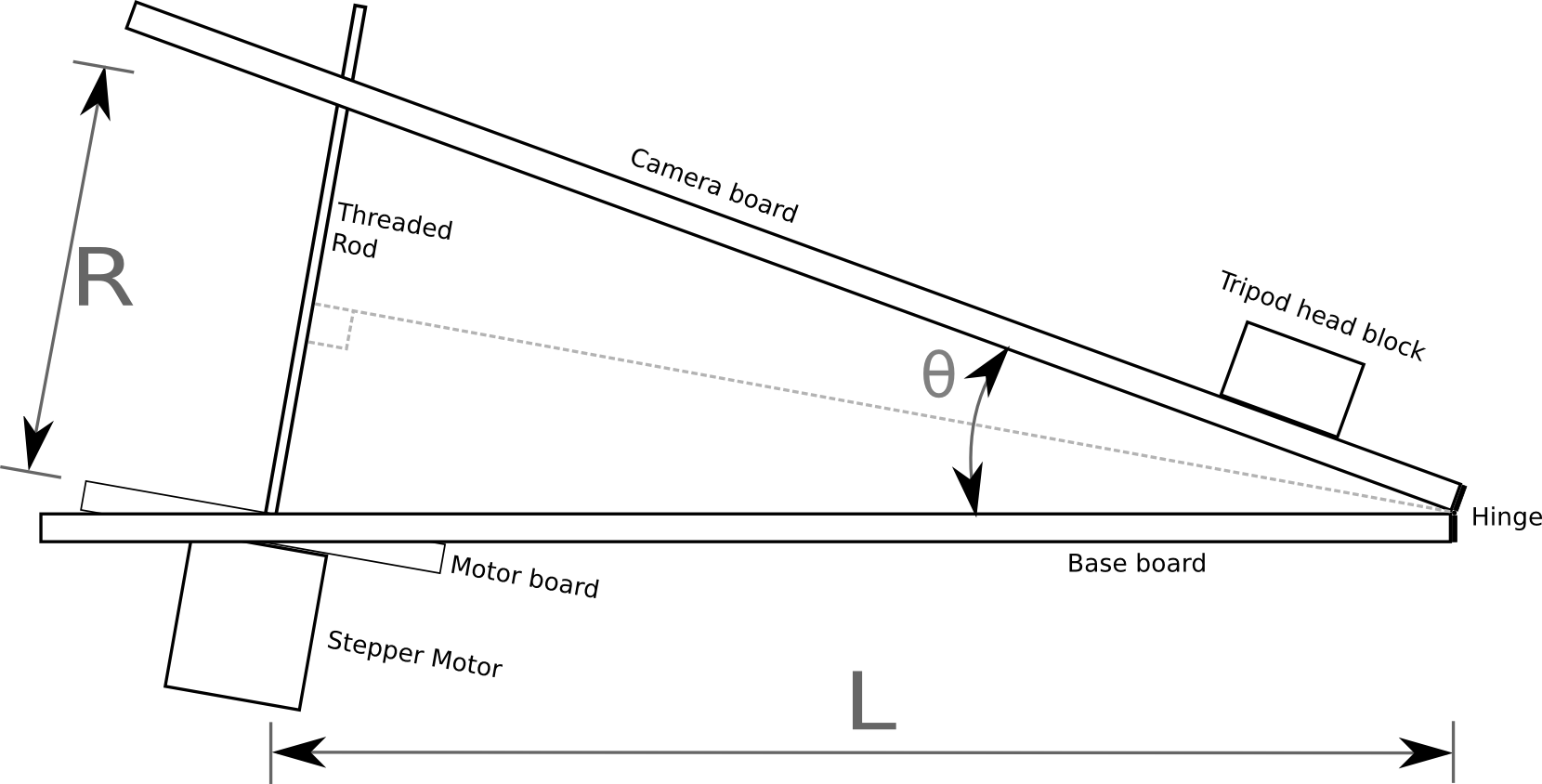
In the above diagram the threaded rod has length R between the two boards, forming an angle θ. It can readily be seen from the diagram that the isosceles triangle formed by the two boards and the rod can be split into a pair of identical right angle triangles. Basic trigonometry tells us that the sine of the principal angle in a right angle triangle is equal to the ratio between the opposite and hypotenuse:
![]()
In our diagram above, the principal angle is θ/2, the length of the opposite is R/2 and the hypotenuse is L. Plugging those symbols into the first formula we get:
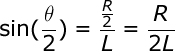
In order to drive the threaded rod, the value we want to calculate is R, so we need to re-arrange the formula to get R on the left hand side:
![]()
The Arduino isn’t directly controlling the length of the rod though, rather it is controlling its rotation. The length of the rod is the ratio between the number of rotations and the number of threads per centimetre. This gives us a second formula for R
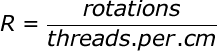
Lets substitute this new formula for R, into the previous formula:
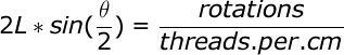
A few moments ago we mentioned that the quantity we actually control is the rotation of the rod, so the formula must be re-arranged to get the number of rotations on the right hand side:
![]()
With this formula, we know how many rotations are needed to achieve a given angle between the boards, but what exactly is the angle we need ? The Earth doesn’t take exactly 24 hours to rotate a full 360 degrees, in fact it is about 23 hours, 56 minutes, 4.0916 seconds. This value is known as the sidereal time or rate. With this information we can now define a formula to derive the value for θ at any given time t, since starting operation of the mount from a closed position:
![]()
Since θ is the value we need, lets re-arrange that formula to get θ on the right hand side
![]()
This formula for θ can now be substituted into the earlier formula for calculating the rotations of the rod:
![]()
The final term can be slightly simplified by removing a factor of 2
![]()
This formula operates in degrees, but when doing calculations in software it is desirable to measure angles in radians. There is a simple formula for converting from degrees to radians:
![]()
With this information it is now possible to update the formula for calculating rotations to operate in radians by substituting in the conversion formula:
![]()
A little while ago it was said that the Arduino is controlling the number of rotations of rod. This isn’t strictly true, it is in fact controlling the number of steps of the motor. A motor will have a certain number of steps it can do in one rotation, which gives a step size in degrees. The formula for calculating rotations can thus be adapted to calculate the number of steps

This is our last formula and it has 4 variables to be filled in with accurate values
- stepsize: the stepper motor used in the electronics does 200 steps per rotation giving a step size of 1.8. This is a common size for this type of stepper motor. Another typical size is 64 steps per rotation.
- threads.per.cm: a standard M8 threaded rod will have 10 threads per centimetre, other rods may vary.
- L: this is the length of the base board between the hinge and the centre of the threaded rod. This has to be precisely measured after construction is complete
- siderealtime: 23 hours, 56 minutes, 4.0916 seconds, or more simply 86164.0419 seconds
This formula could be executed directly on the Arduino board, but a sine calculation is somewhat heavy for the microcontroller. Realistically the mount isn’t going to be doing exposures of longer than 2-3 hours. It is fairly trivial to thus this formula and calculate the required number of rotations for each minute of each hours and produce a 180 entry table. The Arduino then merely has to keep track of time and do a trivial table lookup to determine the rotation rate. An algorithm for doing this will be the subject of a later blog post.
Now read: part 3, drive control software