Part 1, part 2 and part 3 of this series consider the electrical circuit construction, mathematics behind the drive mechanism, and the control software code. In this post it is time to consider the physical construction of the barn door mount. The logical diagram from part 1 should give a good idea of what the mechanical design will look like, so without further ado lets look at a set of diagrams that reflect the physical construction design that was actually done
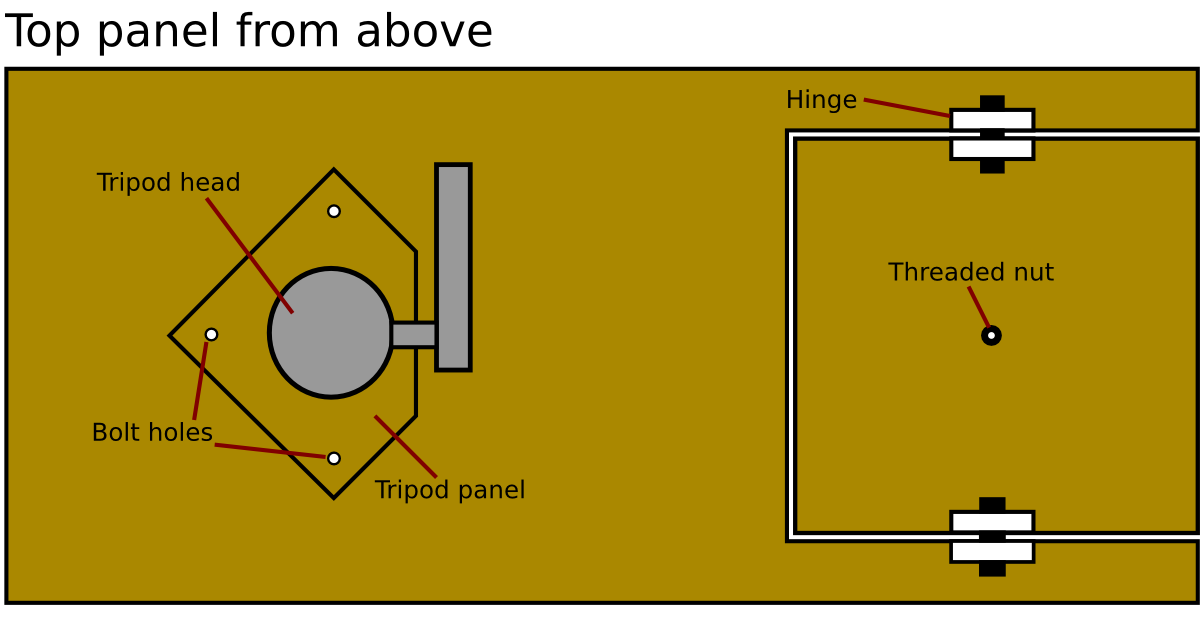
First, looking at the top panel of the mount from above. On the right hand side of the panel, a square section was cut out and then re-attached to the main panel with a pair of pivots. These were actually furniture fixing blocks connected by a bolt and with nylon washers to act as spacers between. In the center of the cut out is an M8 threaded nut, glued in place with epoxy resin, through which the threaded rod will rotate during operation. The alignment of the pivoting hinge and thread nut is crucial to allowing the cut out panel to pivot correctly. On the left hand side of the main panel is the tripod head for attaching the camera to the mount
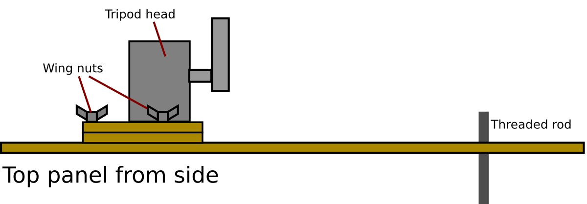
 The tripod head attachment is better seen from the side view of the top panel. The tripod head could not be mounted directly to the main panel, because that would not allow sufficient clearance for the handle to be turned. So two small wooden panels were cut to raise the tripod head a couple of centimetres up from the panel. The tripod head is bolted to one of these small panels with a 3/8″ bolt, and both panels are then bolted down to the main panel using 3 bolts and wing nuts for easy release.
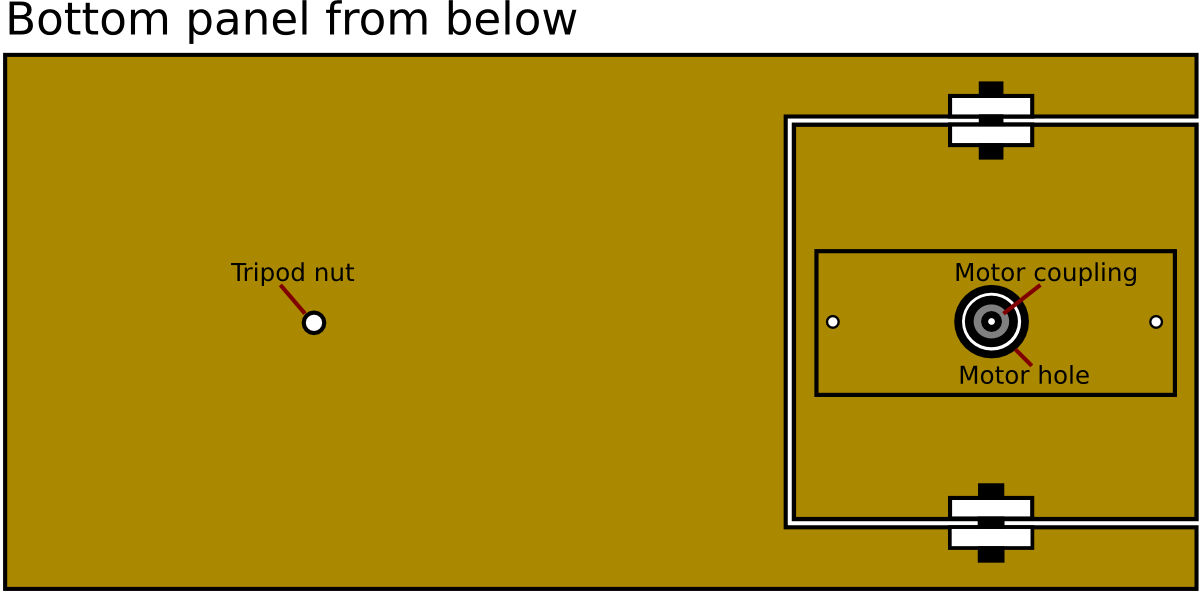
Moving on to the bottom panel, as viewed from below. Again there is a square cut out panel attached to the main panel with a pair of pivoted bolts. On the left hand side there is a hole in which a 1/4″ captive nut is glued in place from above using epoxy resin. When the tripod is attached it will thus be trying to pull the capture nut through the board which is impossible, thus ensuring a strong connection. This is critical, because the entire weight / torsional load of the barn door mount will be on this captive nut. The pivoting panel has the stepper motor attached to it. The stepper motor is connected to the threaded rod using a flexible coupling nut. To enable the top and bottom panel to get to the 100% closed position, the coupling needs to be recessed somewhat, so the motor is not attached directly to the pivoting panel.
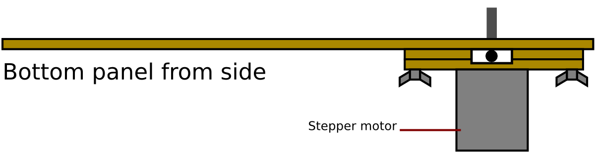
The side view of the bottom panel shows the motor attachment more clearly. Two smaller pieces of wood are used as spacers, to which the stepper motor is attached using M3 machine bolts. These spacers are then attached to the main pivoting panel with a pair of M6 bolts and wing nuts for easy release.
Finally, a length of continuous “piano hinge” is used to connect the top and bottom panels together on the left hand edge. The top and bottom panels are approx 35cm by 18cm each, and using 12mm thick plywood. The pivoting panels are approx 12cm square cut-outs. As noted in previous blog posts the exact dimensions aren’t critical, since the control software can be tuned to rotate at whatever rate is required for the final build dimensions.
The parts list for the construction was
- Tripod head. (used a cheap Chinese Manfrotto knock-off “Manbilly”)
- 1/4″ captive nut (to accept primary tripod in bottom panel)
- 3/8″ bolt (to connect tripod head on top panel)
- M6 machine screws (x2 for motor panel, x4 for pivot hinges and x3 for tripod head panel)
- M6 wing-nuts (x2 for motor panel, x3 for tripod head panel)
- M6 nuts (x4 for pivot hinges)
- M6 nylon washers (x4 for pivot hinges)
- M8 threaded rod 35cm length
- M5xM8 flexible coupling (5mm x 8mm – see part 1)
- Sheet of plywood (approx 100cm x 50cm x 12mm)
The cost of these parts will vary depending on what you’ve got handy in your toolbox already and whether you have a cheap DIY store locally. The most expensive part was the tripod head, hence why I used a cheap knockoff. The nuts & bolts were just a few pounds and the sheet of plywood was an off-cut from the local DIY store obtained for just a few pounds too.
Now read: part 5, the finished device.