Tag Archives: moon

Processing workflow for lunar surface images using GIMP and G’MIC

This post is going to illustrate a post-processing workflow for lunar surface images using the open source tools GIMP and G’MIC. GIMP has been largely ignored by astrophotographers in the past since it only supported 8-bit colour channels. The long awaited GIMP 2.10 release in April 2018, introduced 16-bit and 32-bit colour channel support, along with many other important improvements that enable high quality post-processing.

Astrophotographers seeking to present high detail images of The Moon, have long recognised that capturing a single still image is not sufficient. Instead normal practice is to capture a high definition video at a high frame rate lasting for a minute or more, by attaching a webcam to a telescope in place of the eyepiece. A program such as AutoStakkert2 will then process the video, analysing the quality of each video frame, selecting the “best” frames, and then merging them to produce a single frame with less noise and more detail. The output of AutoStakkert2 though is not a finished product and requires further post-processing to correct various image artefacts and pull out the inherent detail. A common tool used for this is Registax which particularly found popularity because of its wavelet sharpening feature.

Use of AutoStakkert2 can be a blog post in its own right, so won’t be covered here. What follows will pick up immediately after stacking has produced a merged image, and show how GIMP and G’MIC can replace use of the closed source, Windows based Registax tool.

The source material for the blog post is a 40 second long video captured with a modified Microsoft Lifecam HD paired with a Celestron Nexstar 4GT telescope. Most astrophotographers will spend £100 or more on CCD cameras directly designed for use with telescopes, so this modded Lifecam is very much at the low end of what can be used. This presents some extra challenges, but as can be seen, still allows for great results to be obtained with minimal expense.

The first noticeable characteristic of the video is a strong pink/purple colour cast on the edges of the frame. This is caused by unwanted infrared light reaching the webcam sensor. A IR cut filter is attached to the webcam, but it is positioned too far away from the CCD chip to be fully effective. A look at a single video frame at 100% magnification shows high level of speckled chromatic noise across the frame. Finally the image slowly drifts due to inaccurate tracking of The Moon’s movement by the telescope mount and features are stretched and squashed due to atmospheric distortion.

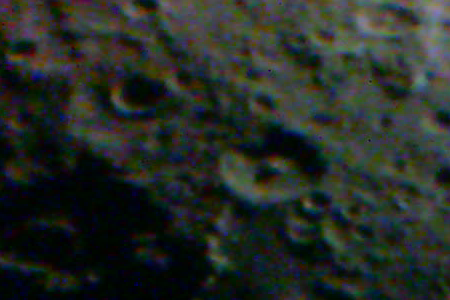
100% magnification crop of a single still video frame before any processing

After the video frames are stacked using AutoStakkert2, the resulting merged frame shows significant improvements. The speckled noise has been completely eliminated by the stacking process which effectively averages out the noise across 100s (even 1000s) of frames. The image, however, appears very soft lacking any fine detail and there is chromatic aberration present on the red and blue channels

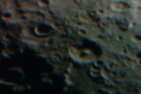
100% magnification crop after stacking top (50% by quality) video frames in AutoStakkert2

AutoStakkert2 will save the merged image as a 16-bit PNG file, and GIMP 2.10 will honour this bit-depth when loading the image. It is possible to then convert it to 32-bit per channel before processing, but for lunar images this is probably overkill. The first task is to get rid of the chromatic aberration since that has the effect of making the image even softer. With this particular webcam and telescope combination it is apparent that the blue channel is shifted 2 or 3 pixels up, relative to the green, while the red is shifted 2 or 3 pixels down. It is possible to fix this in GIMP alone by decomposing the image, creating a layer for each colour channel, then moving the x,y offset of the blue and red layers until they line up with green, and finally recomposing the layers to a produce a new colour image.

This is a rather long winded process that is best automated, which is where G’MIC comes into play. It is a general purpose image processing tool which has the ability to run as a GIMP plugin, providing more than 450 image filters. The relevant filter for our purpose is called “Degradations -> Chromatic Aberrations“. It allows you to simply enter the desired x,y offset for the red and blue channels and will re-align them in one go, avoiding the multi-step decompose process in GIMP.

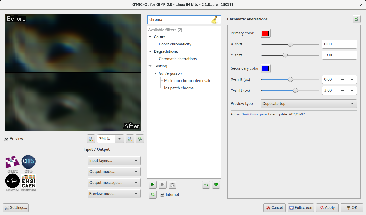
G’MIC Chromatic Aberration filter. The secondary colour defaults to green, but it is simpler if it is changed to blue, since that is the second fringe colour we’re looking to eliminate. The preview should be zoomed in to about 400% to allow alignment to be clearly viewed when adjusting x,y offsets.

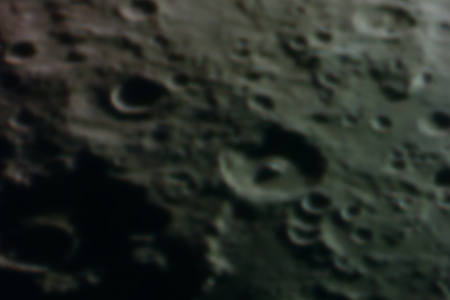
100% magnification crop after aligning the RGB colour components to correct chromatic aberration.

With the chromatic aberration removed the next step is to get rid of the colour cast. The Moon is not a purely monochrome object, with different areas of its surface have distinct colours which would ideally be preserved in any processed images. Due to the limitations of the camera being used, however, the IR wavelength pollution makes that largely impossible/impractical. The only real option is to desaturate the image to create an uniformly monochrome image. If a slightly off-grey colour tint is desired in the end result, that could be added by colourizing the final image.

100% magnification crop after desaturating to remove colour cast due to IR wavelengths

The image that we have at this stage is still very soft, lacking in any fine detail. One of the most popular features in Registax is its wavelet based sharpening facility. Fortunately there are a number of options available in GIMP now that can achieve comparable results. GIMP 2.10 comes with a “Filters -> Enhance -> Wavelet decompose” operation, while G’MIC has “Details -> Split Details (wavelets)” both of which can get results comparable to Registax wavelets operating in linear mode. The preferred Registax approach though is to use guassian wavelets, and this has an equivalent in G’MIC available as “Details -> Split Details (gaussian)“. The way the G’MIC filter is used, however, is rather different so needs some explaining.

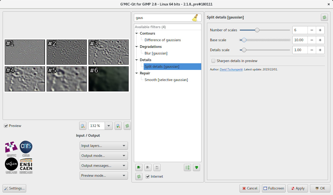
Split details (gaussian) filter. The image will be split into 6 layers by default, 5 layers of detail and a final background residual layer. Together the layers are identical to the original image. The number layers together with the two scale settings determine the granularity of detail in each layer. The defaults are reasonable but there’s scope to experiment if desired.

Describing the real mathematical principals behind gaussian wavelets is beyond the scope of this posting, but those interested can learn more from the AviStack implementation. Sticking to the high level, when the plugin is run it will split the visible layer into a sequence of layers. There is a base layer “residual” and then multiple layers of increasingly fine details applied with “Grain Merge” mode. Taken together these new layers are precisely equivalent to the original image.

The task now is to work on the individual detail layers to emphasize the details that are desired in the image, and (much less frequently) to de-emphasize details that are not desired. To increase the emphasis of details at a particular level, all that is required is to duplicate the appropriate layer. The finest detail layer may be duplicated many, many, many times while coarse detail layers may be duplicated only once, or not at all. If even one duplication is too strong, the duplicated layer opacity can be reduce to control its impact.

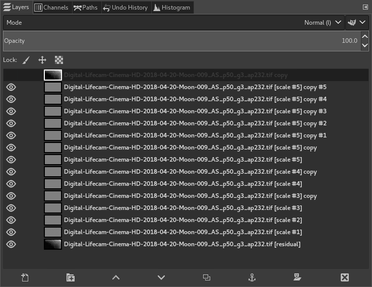
GIMP layers. The default G’MIC split details filter settings created 6 layers. The layer labelled “Scale #5” holds the fine details and has been duplicated 5 times to enhance fine details. The “Scale #4” and “Scale #3” layers have both been duplicated once, and opacity reduced on the “Scale #3” duplicate.

It is recommended to work in order from coarsest (“Scale #1”) to finest (“Scale #5”) detail layers, and typically the first two or three levels of details would be left unchanged to avoid unnatural looking images with too much contrast. There is no perfect set of wavelet adjustments that will provide the right amount of sharpening. It will vary depending on the camera, the telescope, the subject, the seeing conditions, the quality of stacking and more. Some experimentation will be required to find the right balance, but fortunately this is easy with layers since changes can be easily rolled back. After working on an image, ensure it is saved in GIMP’s native XCF format, leaving all layers intact. It that then be revisited the following day with a fresh eye whereupon the sharpening may be further fine tuned with benefit of hindsight.

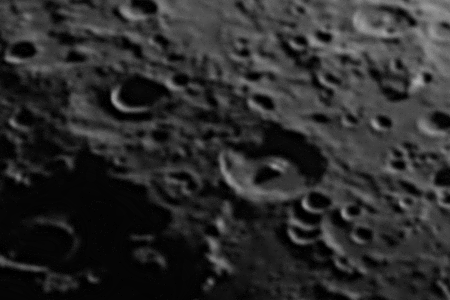
100% magnification crop after sharpening using G’MIC gaussian wavelets filter and GIMP layer blending

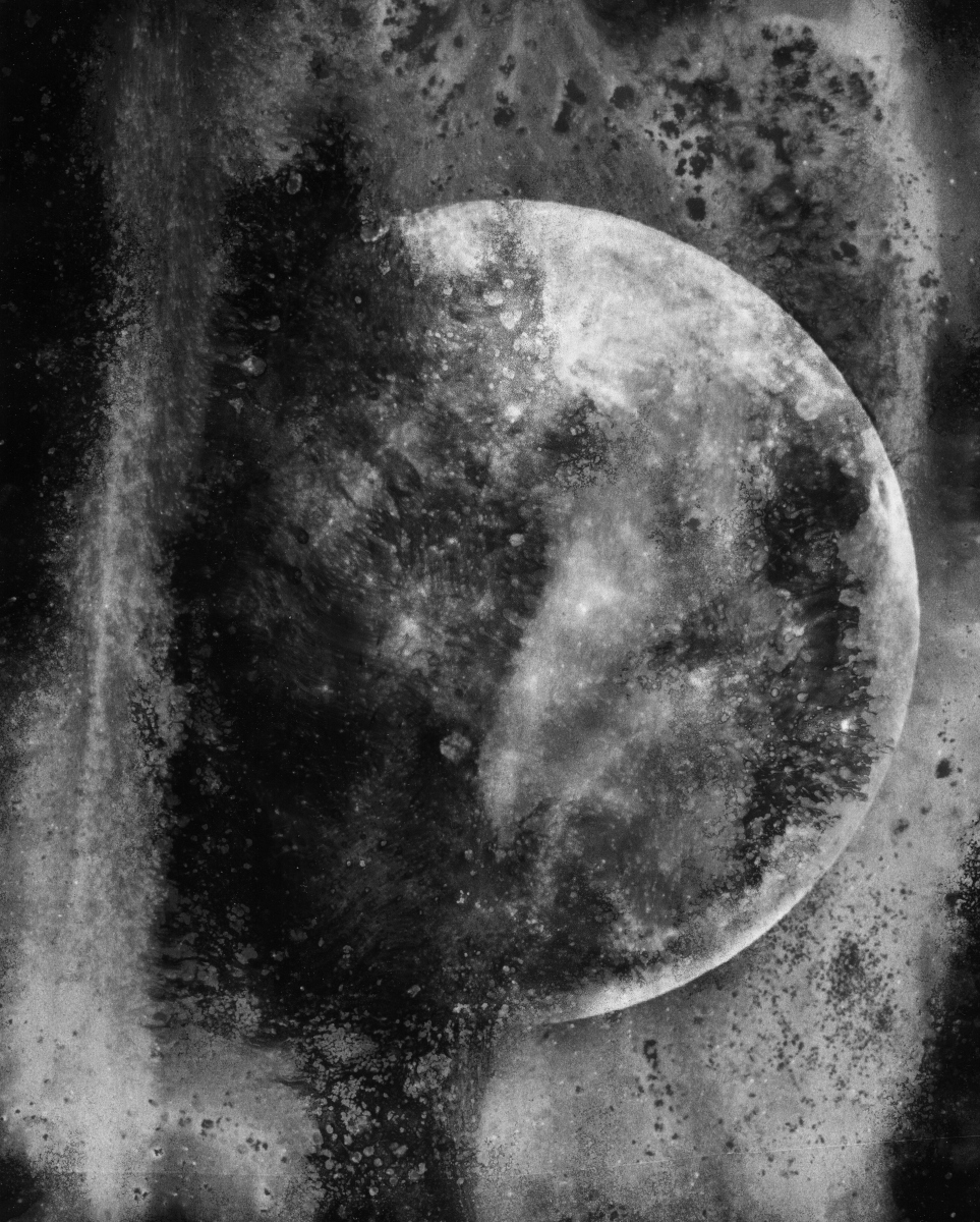
As the image below shows, even with a modified webcam costing < £20 on a popular auction site, it is possible to produce high detail images of The Moon’s surface, using open source tools for all post-processing after the initial video stacking process.

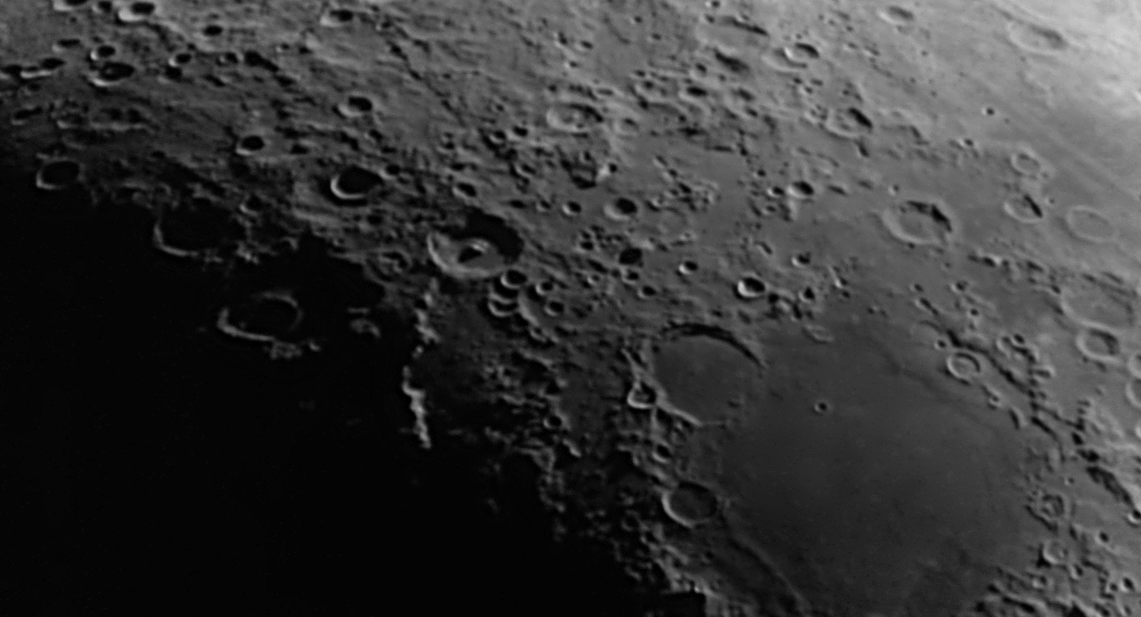
Complete final image after all post-processing


Creating chemigram images with caffenol ingredients

Over the past year or two I’ve done a bunch of experiments with the Chemigram process and even combined it with the Lumen process. In the work so far I’ve used various different substances as resists to control the action of the developer and fixer on the paper, thus influencing the pattern of the light & dark regions. Meanwhile for film processing at home I have been using my Caffenol-C-H-UK recipe almost exclusively as the developer. Caffenol is not just for film, it can be used for developing paper too and it occurred to me one day that instead of mixing up the caffenol in a jug, it might be interesting to just let the caffenol ingredients mix and react directly on the paper. So began a new series of chemigram experiments without using any kind of resist at all.

Caffenol is made by mixing washing soda crystals, vitamin C, instant coffee and optionally some iodized salt. The coffee and vitamin-C are the developing agents while the washing soda acts as an accelerator. The first step was to make a solution of washing soda and water and thoroughly soak the sheets of paper in it. The granules of instant coffee can be placed individually on the paper where needed, or simply sprinkled in an adhoc manner. The vitamin-C powder can just be poured or sprinkled onto the paper. The theory is that when the coffee/vitamin-c hits the wet paper it reacts with the washing soda to form caffenol on the surface. This is done in normal lighting conditions so the paper is universally and totally exposed and should gradually turn black where the caffenol has formed.

For this first test I used off-cuts of some outdated ~|40 year old) Ilford FB paper approx 5×4 inches in size. It was soaked in warmed (~25 C) washing soda solution then some coffee was sprinkled on, followed by some vitamin-C powder. After a minute or so it is possible to see hints of development along the edges where the paper is going dark gray

Caffenol chemigram initial stateAfter 5 minutes the developed areas didn’t appear to be getting any darker. I figured that since the paper was quite lightweight and moderately glossy, it was probably not able to absorb very much of the washing soda solution thus limiting how much caffenol can form. The washing soda is critical as an accelerator, without it coffee/vitamin-C are far too slow. So to try and intensify things I used a syringe to squirt on some more washing soda, which made the vitamin-C fizz very nicely. This image shows the run-off is developing the paper quite efficiently after just a minute or so:

Caffenol chemigram developing

The surprise came when I decided to wash off the ingredients. It turned out that the instant coffee had formed quite a sticky sludge which had adhered well to the paper. Given the limited water holding capacity of the paper, the areas with great concentrations of coffee granules had ironically developed the least. There is just a slight gray speckling effect where the coffee had a very limited action on the silver halides. The areas of most intense development were along the edges where the coffee and vitamin-C had mixed initially, and then in the broad areas of run-off which had well mixed caffenolCaffenol chemigram result

The process was repeated, but without pouring washing soda over the ingredients, just relying in that initially absorbed by the paper. The results were fairly similar to the first test, but with less development of the surrounding paper, as would be expected due to lack of run-off.

Caffenol chemigram resultThe results obtained were partially aligned with the initial expectations of the process but, as always when experimenting, there were surprises. In particular the inability of the paper to absorb sufficient washing soda solution was a key limiting factor in the results. It was surprising to see how the coffee + vitamin-C alone were fairly weak, but when they combined they became stronger than the sum of the parts. Finally the way the coffee became a sticky mass on the surface of the paper actually caused it to act as a chemigram resist, as well as a developer at the same time!

With the initial experiments successfully completed it was time to try some larger scale work with full sheets of 8×10 paper. The goal was really to just do more of the same but on a larger scale. The first work was fairly light on washing soda, thus forming broadly static patterns showing the texture of the vitamin-c powder and coffee granules, though there were some limited areas of runoff creating dynamic swirling patterns

Caffenol chemigramWith the second print the aim to was make a very dynamic image showing the motion of developing liquid on the surface of the paper, at the expense of any fine detail.

Caffenol chemigramPleased with the results of caffenol in a pure chemigram process, I decided to take it a step further and try to combine chemigram with a traditional B&W development process in the darkroom.

A while ago I took an simple photo of the Moon with a DSLR and teleconvertors which I then used to create a digital negative on acetate for printing as a cyanotype. Astrophotography is an increasingly popular endeavour for many people, but almost without exception the aim is to produce images with the best sharpness and finest detail the equipment will allow. An unfortunate result is that any two images of the moon will look broadly alike, and my own astrophotography images of the moon are no exception. So I decided that this digitally captured moon image would provide a good challenge as source material for creating a truly unique photographic print.

In the darkroom under safe light conditions, I placed a sheet of outdated Ilford FB 8×10 paper under the enlarger. The digital negative went on top of the paper for purpose of contact printing. From previous experience contact printing on this paper I just guesstimated the exposure at 15 seconds, with lens at f/8. The paper now has an invisible latent image ready to be worked on by the caffenol.

I soaked the paper in a washing soda solution, randomly sprinkled instant coffee and vitamin-C onto the paper and then just let it sit for a few minutes to give time for the caffenol to start working. Part way through I also added a very small amount more washing soda in some areas to encourage the development. After approximately 3-4 minutes (I wasn’t really timing this) I could see slight hints of the paper starting to turn gray in places. Washing off the caffenol residue though showed almost no development across most of the paper, which was initially disappointing.

None the less I now put the print through a regular B&W dev, stop & fix process. Rather than leaving it in the developer for the full 1 minute though, I noticed it was developing quite fast and choose to just move it to the stop bath when it “looked about right” – about 35 seconds. What was happening was that although not really visible yet, the caffenol had indeed kickstarted the development across the paper and the normal developer was just needing to finish off the process. If I had let the image site in the developer for the full 1 minute it would have been over developed and lost some of the qualities of the caffenol granulation.

The result was thus incredibly pleasing image of the moon, which I hereafter title “Moon through a dirty window”

Chemigram caffenol contact printLooking at the results obtained shows that the idea of using caffenol in a chemigram process has great possibilities for image making. On its own it can be semi-controlled to create attractive abstract images, while when combined with a regular B&W printing process it turn an otherwise plain image into an intriguingly textured pleasing artwork. I’m very much looking forward to getting back in the darkroom to further work through the possibilities this offers

Constructing a filter for solar imaging with a DSLR

In recent months I’ve had an increasing interest in astronomy and astrophotography, to my surprise discovering the Baker Street Irregular Astronomers who hold monthly observing sessions in Regent’s Park – I never imagined it was practical todo astronomy in London’s light polluted sky. I’ve not got as far as purchasing a telescope yet, instead deciding to learn a bit more about the topic first, and experiment to see what I can do with just a DSLR camera. With a Nikkor 180mm prime lens and 2x teleconvertor I was able to produce this image of the Moon

The Moon

The 180mm lens + 2x teleconvertor on the D90’s 1.5 crop factor sensor gives an full frame equivalent of 540mm. This is really the bare minimum acceptable reach for getting images of the moon, with the image above being a pretty aggressive crop down. There are enough pixels for publishing online, but not really sufficient for printing out at any reasonable resolution.

As most people know, by a stroke of good fortune, the Sun and the Moon have the same apparent size when viewed from the Earth (this is how the moon can precisely block out the Sun during an eclipse). Naturally, since I was able to get a nice image of the Moon with the setup described above, I could expect to get a similar sized image of the Sun. Of course looking at, or pointing your camera at, the Sun is an incredibly dangerous thing to do. You absolutely must take care to protect both the camera optics and your eyes if you are going to try solar imaging. There are a variety of solar filters available in the astronomy market with varying characteristics, but for basic full spectrum DSLR imaging, what you want is a filter built with a piece of Baader AstroSolar Safety Film. This is available in A4 sheets from any decent astronomy store, in my case The Widescreen Center, near Baker St.

Baader AstroSolar Safety Film

Baader AstroSolar Safety Film

The pack just contains one fine sheet of film, around which you need to built a mount to hold it in place in front of the lens. This involves a bit of fun with cardboard, scissors, sellotape and a craft knife. The mount will consist of two flat pieces of card with discs cut out to sandwich the film between, and a tube that will fit snugly around the lens barrel. The basic cut out shapes used to construct the mount can be seen in the image below:

The cut-out parts

The cut-out parts

For the front sandwich I decided to use 4mm poster board to get rigidity. The centre cut outs are just a few mm smaller than the lens diameter ensuring the lens front will not be pressing on the relatively delicate solar film. I decided to cut a 3rd piece to act as a front flap cover to protect the film when not in use too. For the tube, I decided to use thin cardboard – something little thicker / stiffer than than commonly used for cereal packets. The first two strips of it are 2 inches wide, while the third has an extra 3/4 of an inch, which is then cut into a series of little flaps. These flaps will be used to attach the collar to the front sandwich.

The first step was forming the tube / collar around the lens. I placed double sided sticky tape along the two strips of cardboard without the flaps. I fastened the first strip snugly around the lens:

Forming the collar

The next two strips of card simply wrap around the first, reinforcing its shape. Finally the outer layer is wrapped in a strip of black duck tape to secure it fully.

With construction of the tube out of the way, we can move onto construction of the front sandwich. The key thing to remember at this step is that we do not want to place the safety film under tension – it is actually desirable if it is a slightly loose / slack and this will not affect the image quality at all. The Baader instructions recommend laying the film on a sheet of tissue paper to protect it from any roughness on your work surface.

The Safety Film

The film is actually highly reflective & silvery – the yellowish colour seen above is caused by the reflection of light from the walls in my house. The two plasterboard pieces need to have one side each, covered in double sided sticky tape. Gently place one piece face down onto the safety film, lightly pressing around the edges to get good contact. Then flip the board over so the safety film is facing up again and place the second piece of board to complete the sandwich. Now bind the whole lot together by wrapping more tape around all the edges, taking care not to touch the area of film visible through the cut out disc. The 3rd piece of poster board for the protective cover can now also be attached with a few more pieces of tape.

The last stage is to attach the lens collar to the front board, with yet more double sided sticky tape. For added strength, I finished it off by adding strips of duck tape along the join between the collar and front boards. If all went the plan, then the result should look something like this

Finished filter

Finished filter

With the camera attached to a tripod, and the filter in place on the front of the lens, the complete setup looks like:

Filter attached to the camera

The weather was looking kind of dicey while I was constructing the filter, with pretty heavy cloud. By the time I had taken a break to eat lunch though, the cloud had cleared enough that the Sun was visible for a few minutes at a time. This allowed an opportunity to try out the newly constructed filter. Before using the filter though, it is essential to verify that the safety film was not damaged during construction. The instructions that come with the film describe the kind of defects to look out for, basically tears, scratches, holes, etc. The check for damage should be repeated again every time you go to use the filter. You cannot be too paranoid when imaging the Sun. For additional safety it is advisable to not directly look through the camera view finder, even when the filter is in place. Instead either use the live view from the LCD screen on the camera, or better yet, tether the camera to a laptop using a USB cable. I chose the latter approach, controlling the camera from a laptop using Entangle.

Actually attempting to take a photo though highlights another challenge – that of lining up the camera so that it points at the Sun, without actually looking at the Sun. To get the initial rough alignment, I adjusted the tripod head so that the camera lens was parallel to one of the tripod legs, then shifted the entire tripod around until the shadow cast by that tripod leg disappeared. With rough alignment achieved, I then enabled “live view” in Entangle and made minor changes to the tripod head until the Sun appeared in the centre of the screen.

Aside from the safety benefit, one of the key reasons to tether the camera to a laptop is that it makes focusing much simpler. The laptop screen can zoom the preview image until it shows pixels at 1-1 size. Very small tweaks of the lens focusing ring can then bring focus into the sweat spot. The result of all this work, was the following image

The Sun

Click on the image above to be taken across to flickr where it can be viewed full size. The white colour is the result of the of the Baader film doing its job. If a traditional “yellow” image is desired, it is a simple matter of adding colourization when post-processing the image. The handful of dark smudges in the bottom left quarter of the image are sunspots.

Overall the construction of the filter took somewhere between 1+1/2  and 2 hours (I wasn’t timing it so don’t know the exact time). When viewed with normal full spectrum light, the Sun does not produce anywhere near as interesting an image as the Moon. It was none-the-less satisfying to be able to capture the sunspots. The limiting factor to producing a better image at this point is likely the need to get a longer focal length lens. As mentioned earlier the setup used for this image, was equivalent to about 540mm. If I can switch the Nikkor 180mm lens out for something like the Sigma 150-500mm lens, it would be able to get to 1500mm full frame equivalence. Of course, first I’ll have to buy the Sigma, and then go through the process of building another filter to fit that lens, since its diameter is no doubt different to that of the Nikkor 180mm. Those who really get addicted to solar imaging will end up buying dedicated scopes with Hydrogen-Alpha or Calcium K-Line filters, which produce some really stunning images.