Category Archives: Tutorials

Building a UV LED light box for cyanotype and lumen printing

The cyanotype and lumen printing processes are two of the more frequently practised alternative photographic processes, because of their overall simplicity and the fact there is little-to-no need for equipment. Most people will do their exposures outside in the Sun initially, but if you want to work with these processes on a regular basis it can be frustrating to have ideas ready to try, but be delayed by lack of a sunny day. While it is still possible to expose on cloudy days, the length of time required to obtain a suitable image is greatly increased. Working with the sun it is also difficult to figure out predictable exposure times as the intensity varies according to the daily weather, time of day and time of year.

The solution is to switch to an artificial UV light source which can be used any time of day or year, whatever the weather, always giving the same exposure time. Historically though, UV exposure units have been relatively expensive to obtain, £100 or more. The ongoing developments in LED lighting technology though have now opened up new possibilities for constructing a custom UV light source for minimal cost. In particular it is possible to obtain 5m long strips holding 300 UV LEDs from online marketplaces such as eBay, for around £15 / $20 (search eBay for keywords “5M UV 5050 SMD 300LED“).

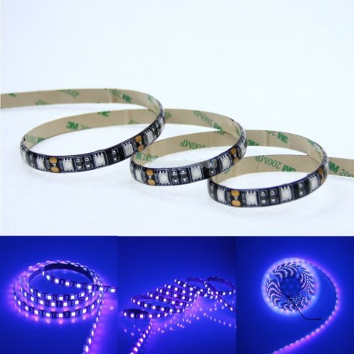
 5M UV (395-405nm) waterproof 5050 SMD 300LED strip, powered by a 12 V @ 5 amp supply

5M UV (395-405nm) waterproof 5050 SMD 300LED strip, powered by a 12 V @ 5 amp supply

The 5M long 5050 LED strips are 1cm in diameter and can be cut every 3rd LED. If they are cut into groups of 15 LEDs, this will result in 20 LED strips, each 25 cm long. Arranged side by side, this allows for creating a light source that will evenly expose a 20 cm x 25 cm area which is practically perfect for both A4 and 8x10in paper sizes. If one didn’t mind lower intensity it would be possible to left a 1cm gap between strips producing a source suitable for 16x20in / A3 paper, at the cost of longer exposure times.

When cutting the LED strip up, it is important to cut exactly in the middle of the metal contacts between every 3rd LED, as it will shortly be necessary to solder wires onto the metal contacts. If using the waterproof coated LED strip, the rubbery coating will have to be removed from the contact pads after cutting, which is quite tedious and an argument in favour of the non-waterproof variants. With the strip cut into pieces, it is now time to connect them back together by soldering short (5-10 cm length) wires between the metal pads. While it is possible to wire them all together in series to form one long strip, this means the link wires will be carrying the full 5 amp current load and if any link goes bad it risks taking out the entire set of LEDs beyond it. A better bet is to wire them up in parallel, or perhaps grouped in a mesh giving multiple paths for the current, so the link wires only need handle a tiny current and there is redundancy. The important thing when soldering the link wires is to preserve the polarity between strips – ie connect positive to positive, and ground to ground.
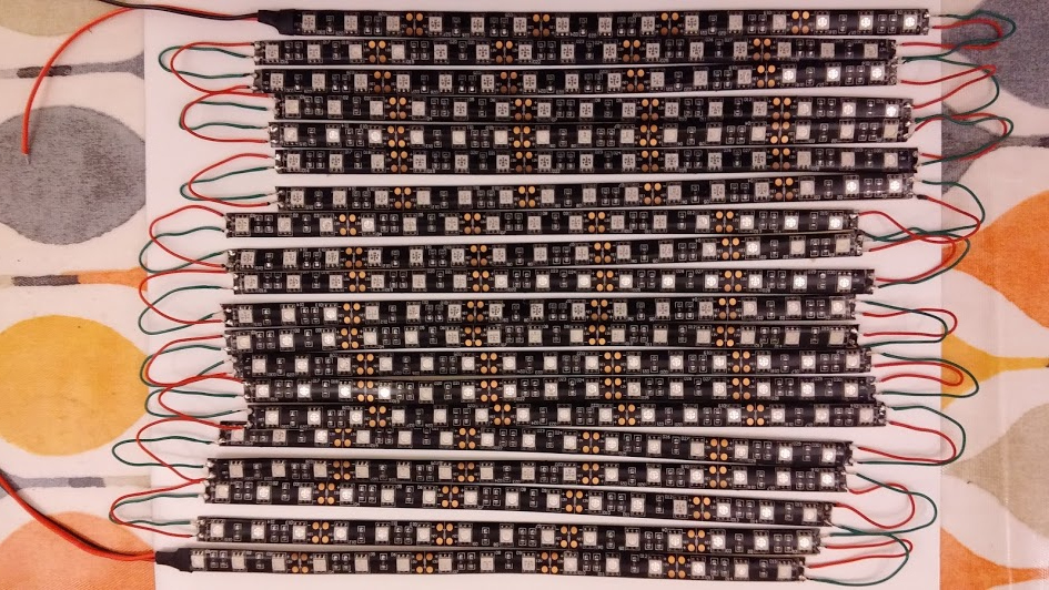
All 20 strips with connecting wires soldered on. Mistakenly all 20 strips are in series. This was later resoldered to put them in parallel

All 20 strips with connecting wires soldered on. Mistakenly all 20 strips are in series. This was later resoldered to split them in 5 groups of 4 strips, each group in parallel, reducing current in the link wires to 1amp.

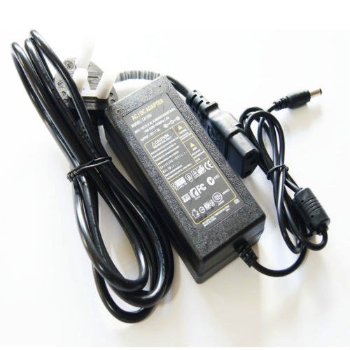
The vendors of the LED strips will typically also sell suitable power supplies. These mains powered units need to output 12 volts and be capable of supplying 5 amps to enable the LEDs to run at full brightness. Lower amperage PSUs will work, but the reduced LED intensity will obviously increase exposure times, so it is best to simply get the right specification of PSU from the start.

Mains PSU for the LED strip able to supply 12 volt at 5 amp

Mains PSU for the LED strip able to supply 12 volt at 5 amp

The power supply will likely have either a 2.5mm or 2.1mm plug, so a correspond matching socket needs to be purchased. While it is possible to just turn the device on/off at the wall, or by pulling the plug out, a better bet is to put a rocker switch inline with the positive power line between the plug socket and the LED strip. Again make sure the rocker switch is rated to carry 5 amps.

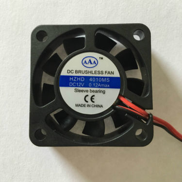
Power output is given by multiplying voltage by current, so 12 volt at 5 amps will produce 60 watts of power output. This is going to generate a reasonably large amount of heat and if something is not done about this, it will gradually degrade the LEDs shortening their lifetime. The obvious answer to this is to obtain a couple of 12 volt computer fans to fit in the case of the final light box. A fan that is approximately 4cm x 4cm in diameter will be ideal. They’re quite cheap so you might even consider using a pair of fans. The wires from the fan can be connected in parallel with the LED strips, since they’re conveniently driven from the same voltage. Do NOT connect them in series with the LEDs, as the 5 amp current draw of the LED circuit will kill the fans. Also be careful to get the positive/ground polarity right when connecting the fan, as reversing polarity will NOT make the fan run in reverse and likely kill the fan too.

12 volt computer fan, 4cm in diameter

12 volt computer fan, 4cm in diameter

The case for the light box will be made out of wood and comprise two pieces, a base which will hold the paper to be exposed and a slightly larger lid which will hold the LED panel. Both will have sides and be sized so that the base nests snugly inside the lid (or vica-verca). The top and bottom panels can both be cut from a sheet of 3mm plywood, the lid panel being 39×30.5cm and the base panel 36.5×25.5cm. These sizes are fairly arbitrary – the smaller simply needs to be about 2 inches larger than the size of paper to be exposed on each side. So for 8×10 paper, the smaller would want to be about 12×14 inches. For the larger lid, sides were cut from a length of 70x18mm timber, and nailed to the plywood panel. For the smaller base, sides were cut from a length of 36x10mm timber. In the timber sides of the lid, two 4x4cm holes were cut to hold the fans. Two holes were also drilled in the lid, one for the power supply plug socket and the other for the on/off rocker switch. When inserting the fans in the case, one should be oriented so that it sucks air into the case while the other should blow air out of the case, creating good airflow across the LED panel.
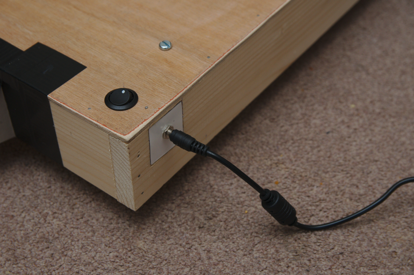
Light box lid showing the on/off rocker switch through the panel and power supply socket in the side
Light box lid showing the on/off rocker switch through the panel and power supply socket in the side

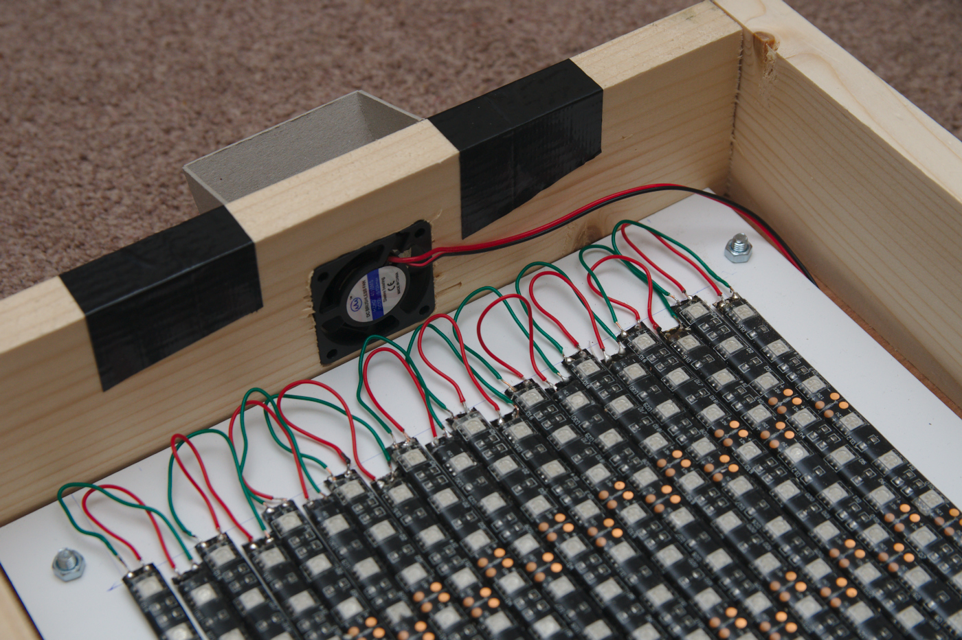
Close up of the lid, showing the computer fan inserted in the side to pull air across the LEDs for cooling.

The LED strip usually comes with a self-adhesive backing tape which is supposed to be able to stick the LEDs to most surfaces. This proved insufficiently sticky for me, so I applied super-glue instead. While the LED strips could be attached directly to the lid of the light box, it was thought preferable to attach them to a sheet of perspex or aluminium to allow the LED sheet to be separated from the case if needed. If using metal just be careful to avoid any short circuits with the link wires of the LED. Once the LEDs are attached, the sheet can be fixed to the inside of the lid with a couple of screws.
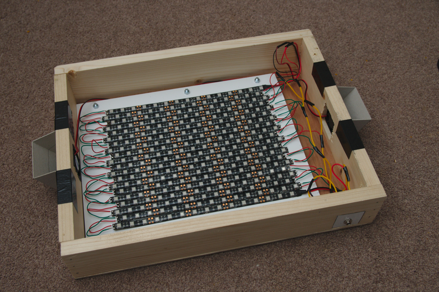
The larger lid, showing the metal plate with LED strips attached. At either end are cardboard shields to block UV light leakage through the fans.
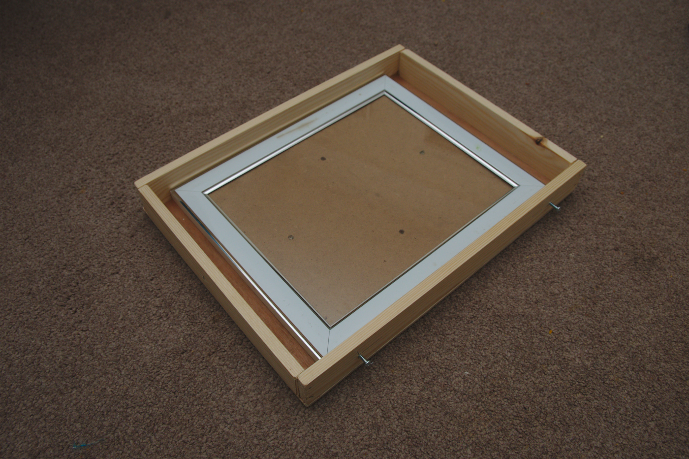
The light box base

The smaller lightbox base, sized to be able to hold an 8×10 inch picture frame from a pound shop. Note a couple of screws sticking out of each side of the base, to prevent it sliding completely inside the lid when nested

When first turning it on, there was some UV light leakage through the cooling fans. Thus a couple of shields were cut from heavy duty cardboard and duct taped over the fan openings. With this in place there is no significant UV leakage from the light box, due to the closely nested lid and base. The UV LEDs are emitting at the end of the UVA spectrum, quite close to the start of the visible light spectrum, so the light is not a serious danger like UVB light would be, but it is none the less worth taking care to avoid accidental exposure.

In use the light box has proved to be intense enough to expose acceptable cyanotype images in as little as 5 minutes, and lumen images in anywhere from 10 minutes upwards depending on the visible effect desired. This is considerably faster than many commercially obtainable UV light sources that photographers have used in the past, which could take 15 to 30 minutes or even more. All together the cost of the complete box was probably around £45 – if you already have some parts in the shed such as plywood / timber pieces and a suitable power supply, then the price could be around £20-25. Either way, it will easily beat the cost of commercially produced light boxes and likely perform better too. The hardest part in construction is probably the soldering of the 50+ link wires between the LED strips. The case needs only minimal wood working skills – use of a saw and hammer. In summary creation of the light box is a very worthwhile use of time and money and will proof useful for years after.
Creating star trails with automatic sky glow removal

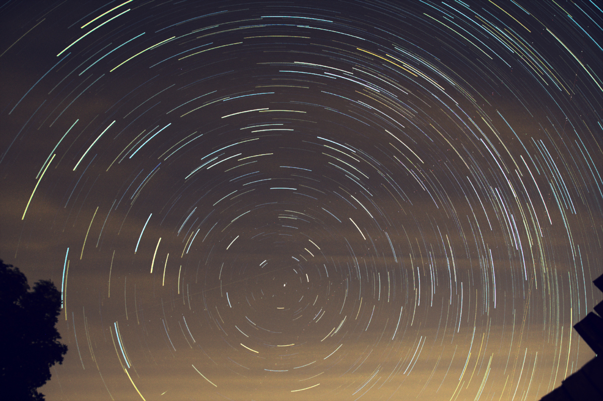
Creating star trail images is one of the easier astrophotography tasks there is, since it doesn’t require any messing about with tracking devices. You just set a camera to point skywards, with programmable remote control set to snap a few 100 images over a hour or more. There are then software programs which can merge the individual images together to create the final star trail. On Linux, I use a startrails plugin for GIMP to perform the merging of individual frames which is simple to use and works pretty well.

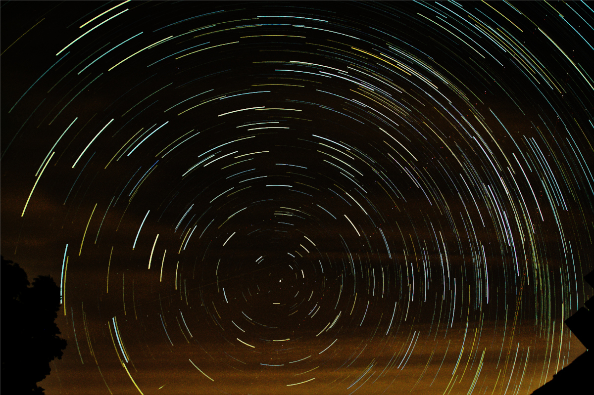
The basic star trail image with no sky glow adjustments applied

The basic star trail image with no sky glow adjustments applied

This is all very straighforward if you’re capturing images under ideal conditions, but life doesn’t always work out that way. The first thing people do is to add in dark frames, which are images captured with the lens cap on. These frames will record any hot pixels or general sensor noise that may be present. The startrail application will merge all the dark frames and then subtract the result from the light frames, removing the hot pixels from the final image.

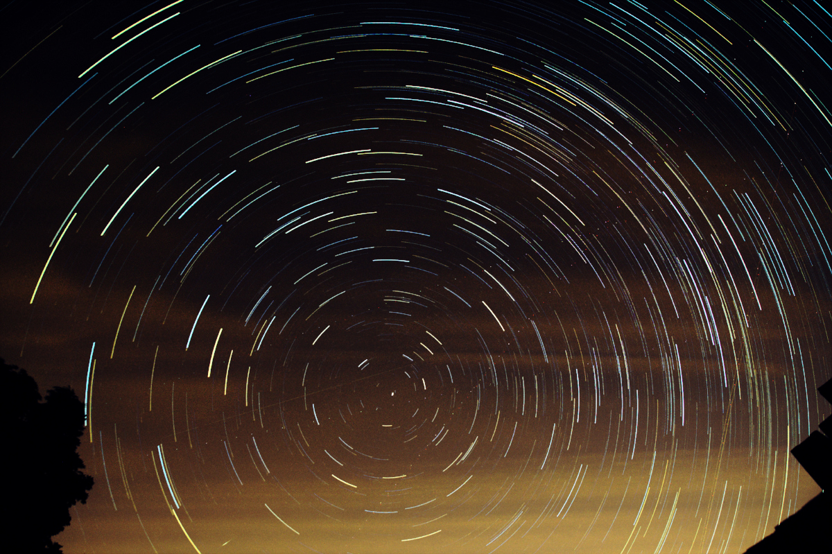
When taking images in London though, there is a major problem with sky glow from the ever present light pollution. There are number of techniques for removing sky glow, with varying pluses and minuses. A simple way is play with the curves/levels to reduce the intensity of the background glow and/or use colour balance corrections to try and make it less noticeable. The problem with this is that the corrections will apply to the background sky, the stars themselves and any foreground objects uniformly. All too often the sky glow is not uniform, but in fact a gradient from top to bottom of the frame, meaning the results of curve adjustment show up the gradient

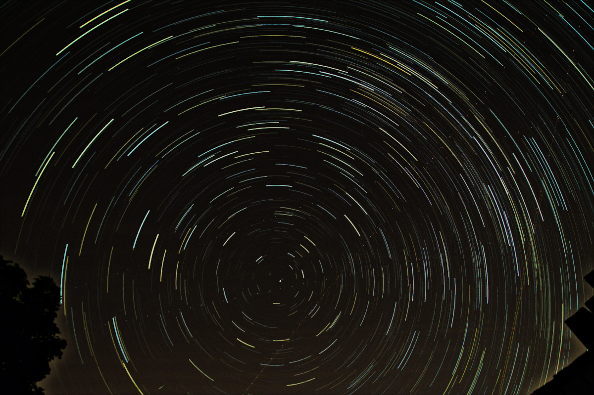
The basic star trail image with curve adjustments to reduce intensity of the sky glow. Due to the gradient, it is only possible to remove part of the sky glow

The basic star trail image with curve adjustments to reduce intensity of the sky glow. Due to the gradient, it is only possible to remove part of the sky glow

The overall goal is to produce a background that is completely black. This could be achieved if we are able to extract the background component from the main image and then subtract it, leaving just the stars behind. The layers feature in any photo editor can be used as mechanism for accomplishing this task.

If we make an assumption that sky glow is approximately the same in each frame, we can follow a simple series of steps to extract a reasonable approximation of the sky glow background. Start by opening one of the individual frames. Then select the menu option Filters -> Blur -> Gaussian Blur. The radius setting should be set to a large value such as 150px. The resulting image should now be a very smooth colour gradient just representing the sky glow background.

A single image frame blurred to leave just the sky glow background

A single image frame blurred to leave just the sky glow background

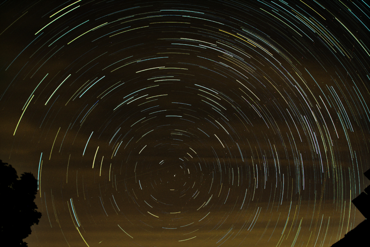
Copy this blurred image, and switch to the star trail image previously produced by the plugin. Create a new layer, paste the blurred image into it and anchor the floating selection. Finally change the layer mode to “Subtract”.

The final star trail image with the gaussian blurred sky glow subtracted

The final star trail image with the gaussian blurred sky glow subtracted

The final result above doesn’t have a completely black background because the sky glow we extracted is merely an approximation, but it should have a less significant colour cast, and lower overall intensity. A small adjustment of curves can further reduce the remaining glow:

The final star trail image with the gaussian blurred sky glow subtracted

The final star trail image with the gaussian blurred sky glow subtracted

While this is much improved, there are still some limitations with this technique. If the sky conditions were changing during the course of the image capture session, any single frame will not be so close to the average glow of the final image, so will either be over or under correcting the sky glow. Weather often plays a part, sending clouds through the scene during capture. Ideally one would simply wait for a clear day before capturing images, but not everyone has such a luxury of time. When some images contain clouds, the final image (as seen above) will have a quite uneven, patchy sky glow which is not easily removed with a simple subtraction layer.

Ideally one would subtract the sky glow from each individual frame before merging them to produce the trail. With 100’s of frames this is quite a tedious process, but since the GIMP startrails plugin is open source GPLv3+ licensed python code, we have the freedom to modify it. To that end I have created a fork which has the ability to perform automatic sky glow removal by applying the gaussian blur technique to each individual frame. This more than doubles the amount of time required to produce a star trail image, but the results are very satisfying indeed.

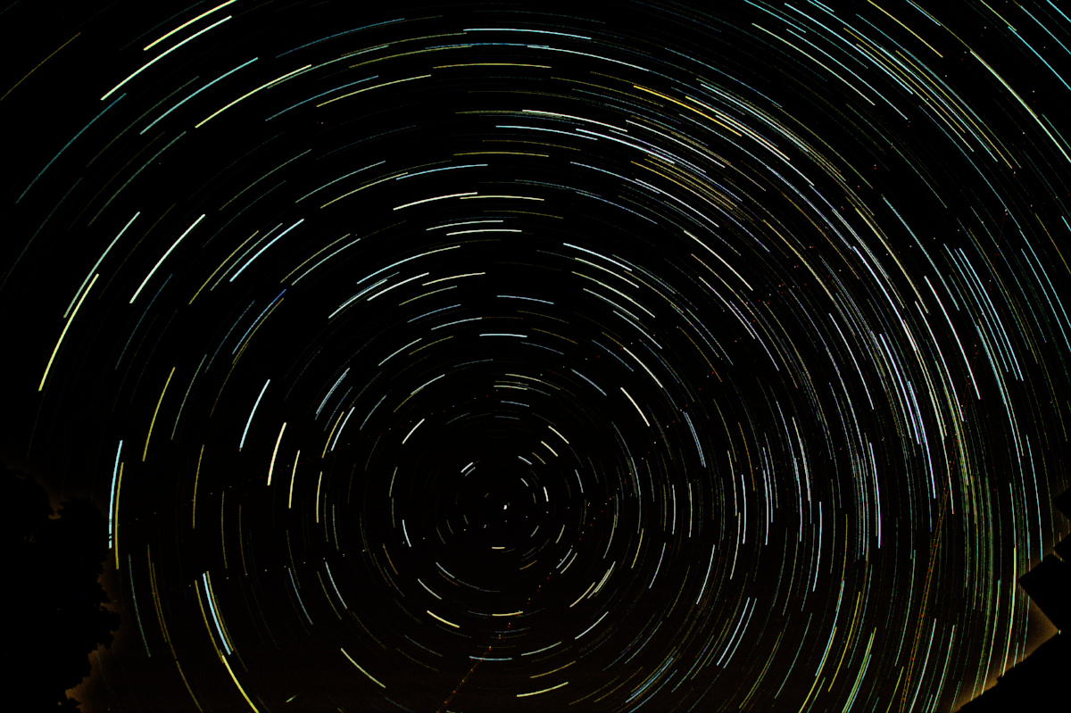
The star trail when sky glow has been subtracted from each individual frame before merging

The star trail when sky glow has been subtracted from each individual frame before merging

The only downside is that when there are foreground images present, they tend to get a halo around their edges. On the plus side, subtracting the sky glow from each individual frame has totally removed the clouds from the image. The background is a pretty dark gray, but not completely black. This can be tweaked with a little use of curves to produce the final image

The star trail when sky glow has been subtracted from each individual frame before merging, with curve adjustments at the edge

The star trail when sky glow has been subtracted from each individual frame before merging, with curve adjustments at the edge

One final tip is to run a guassian blur with a radius of 1.2px on the final image before saving. This will smooth out any jagged edges on the trails caused by the tiny gaps between successive frames.

Creating chemigram images with caffenol ingredients

Over the past year or two I’ve done a bunch of experiments with the Chemigram process and even combined it with the Lumen process. In the work so far I’ve used various different substances as resists to control the action of the developer and fixer on the paper, thus influencing the pattern of the light & dark regions. Meanwhile for film processing at home I have been using my Caffenol-C-H-UK recipe almost exclusively as the developer. Caffenol is not just for film, it can be used for developing paper too and it occurred to me one day that instead of mixing up the caffenol in a jug, it might be interesting to just let the caffenol ingredients mix and react directly on the paper. So began a new series of chemigram experiments without using any kind of resist at all.

Caffenol is made by mixing washing soda crystals, vitamin C, instant coffee and optionally some iodized salt. The coffee and vitamin-C are the developing agents while the washing soda acts as an accelerator. The first step was to make a solution of washing soda and water and thoroughly soak the sheets of paper in it. The granules of instant coffee can be placed individually on the paper where needed, or simply sprinkled in an adhoc manner. The vitamin-C powder can just be poured or sprinkled onto the paper. The theory is that when the coffee/vitamin-c hits the wet paper it reacts with the washing soda to form caffenol on the surface. This is done in normal lighting conditions so the paper is universally and totally exposed and should gradually turn black where the caffenol has formed.

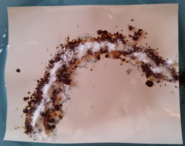
For this first test I used off-cuts of some outdated ~|40 year old) Ilford FB paper approx 5×4 inches in size. It was soaked in warmed (~25 C) washing soda solution then some coffee was sprinkled on, followed by some vitamin-C powder. After a minute or so it is possible to see hints of development along the edges where the paper is going dark gray

Caffenol chemigram initial stateAfter 5 minutes the developed areas didn’t appear to be getting any darker. I figured that since the paper was quite lightweight and moderately glossy, it was probably not able to absorb very much of the washing soda solution thus limiting how much caffenol can form. The washing soda is critical as an accelerator, without it coffee/vitamin-C are far too slow. So to try and intensify things I used a syringe to squirt on some more washing soda, which made the vitamin-C fizz very nicely. This image shows the run-off is developing the paper quite efficiently after just a minute or so:

Caffenol chemigram developing

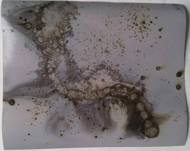
The surprise came when I decided to wash off the ingredients. It turned out that the instant coffee had formed quite a sticky sludge which had adhered well to the paper. Given the limited water holding capacity of the paper, the areas with great concentrations of coffee granules had ironically developed the least. There is just a slight gray speckling effect where the coffee had a very limited action on the silver halides. The areas of most intense development were along the edges where the coffee and vitamin-C had mixed initially, and then in the broad areas of run-off which had well mixed caffenolCaffenol chemigram result

The process was repeated, but without pouring washing soda over the ingredients, just relying in that initially absorbed by the paper. The results were fairly similar to the first test, but with less development of the surrounding paper, as would be expected due to lack of run-off.

Caffenol chemigram resultThe results obtained were partially aligned with the initial expectations of the process but, as always when experimenting, there were surprises. In particular the inability of the paper to absorb sufficient washing soda solution was a key limiting factor in the results. It was surprising to see how the coffee + vitamin-C alone were fairly weak, but when they combined they became stronger than the sum of the parts. Finally the way the coffee became a sticky mass on the surface of the paper actually caused it to act as a chemigram resist, as well as a developer at the same time!

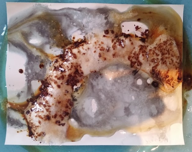
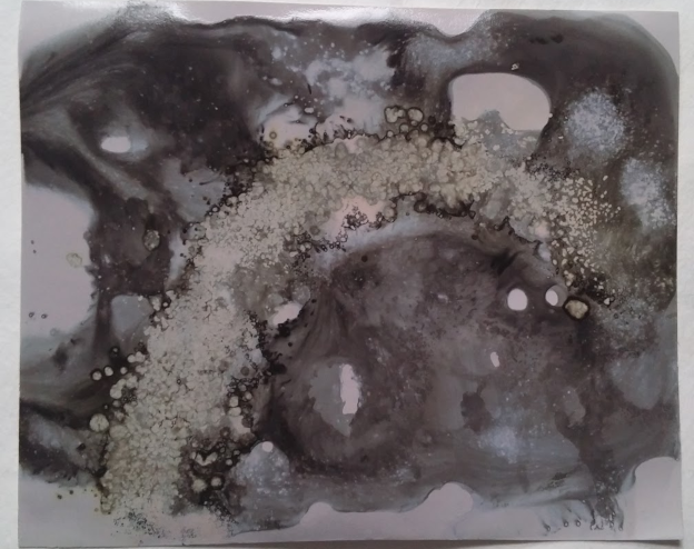
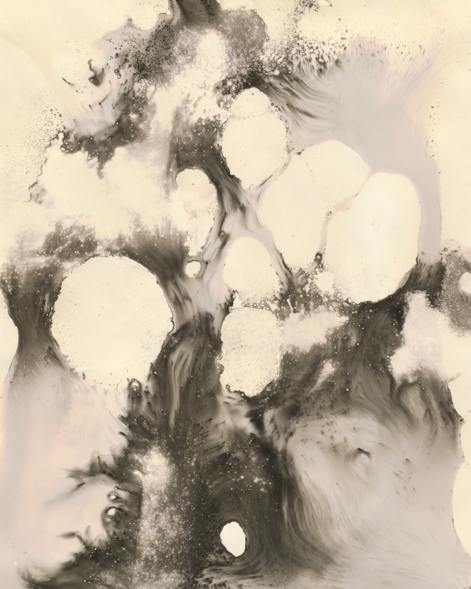
With the initial experiments successfully completed it was time to try some larger scale work with full sheets of 8×10 paper. The goal was really to just do more of the same but on a larger scale. The first work was fairly light on washing soda, thus forming broadly static patterns showing the texture of the vitamin-c powder and coffee granules, though there were some limited areas of runoff creating dynamic swirling patterns

Caffenol chemigramWith the second print the aim to was make a very dynamic image showing the motion of developing liquid on the surface of the paper, at the expense of any fine detail.

Caffenol chemigramPleased with the results of caffenol in a pure chemigram process, I decided to take it a step further and try to combine chemigram with a traditional B&W development process in the darkroom.

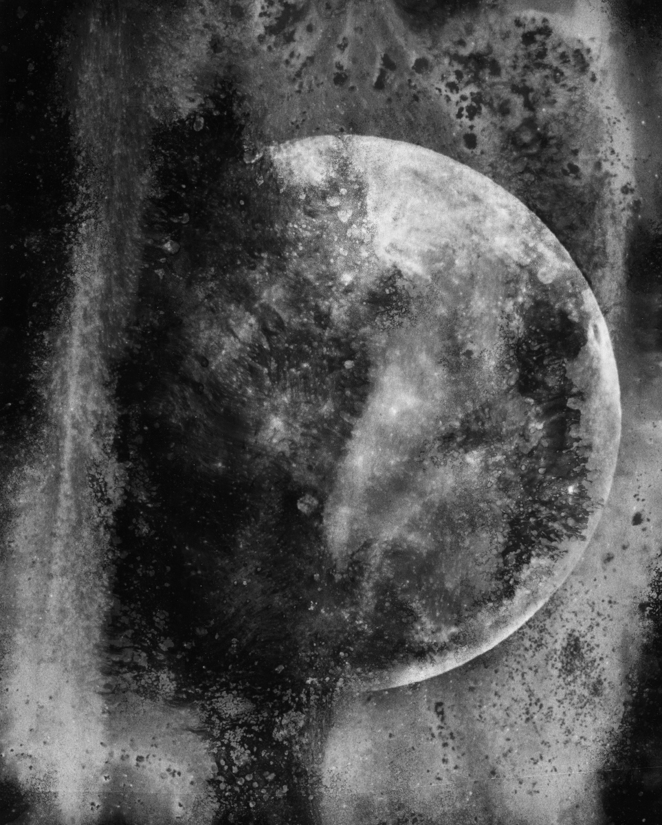
A while ago I took an simple photo of the Moon with a DSLR and teleconvertors which I then used to create a digital negative on acetate for printing as a cyanotype. Astrophotography is an increasingly popular endeavour for many people, but almost without exception the aim is to produce images with the best sharpness and finest detail the equipment will allow. An unfortunate result is that any two images of the moon will look broadly alike, and my own astrophotography images of the moon are no exception. So I decided that this digitally captured moon image would provide a good challenge as source material for creating a truly unique photographic print.

In the darkroom under safe light conditions, I placed a sheet of outdated Ilford FB 8×10 paper under the enlarger. The digital negative went on top of the paper for purpose of contact printing. From previous experience contact printing on this paper I just guesstimated the exposure at 15 seconds, with lens at f/8. The paper now has an invisible latent image ready to be worked on by the caffenol.

I soaked the paper in a washing soda solution, randomly sprinkled instant coffee and vitamin-C onto the paper and then just let it sit for a few minutes to give time for the caffenol to start working. Part way through I also added a very small amount more washing soda in some areas to encourage the development. After approximately 3-4 minutes (I wasn’t really timing this) I could see slight hints of the paper starting to turn gray in places. Washing off the caffenol residue though showed almost no development across most of the paper, which was initially disappointing.

None the less I now put the print through a regular B&W dev, stop & fix process. Rather than leaving it in the developer for the full 1 minute though, I noticed it was developing quite fast and choose to just move it to the stop bath when it “looked about right” – about 35 seconds. What was happening was that although not really visible yet, the caffenol had indeed kickstarted the development across the paper and the normal developer was just needing to finish off the process. If I had let the image site in the developer for the full 1 minute it would have been over developed and lost some of the qualities of the caffenol granulation.

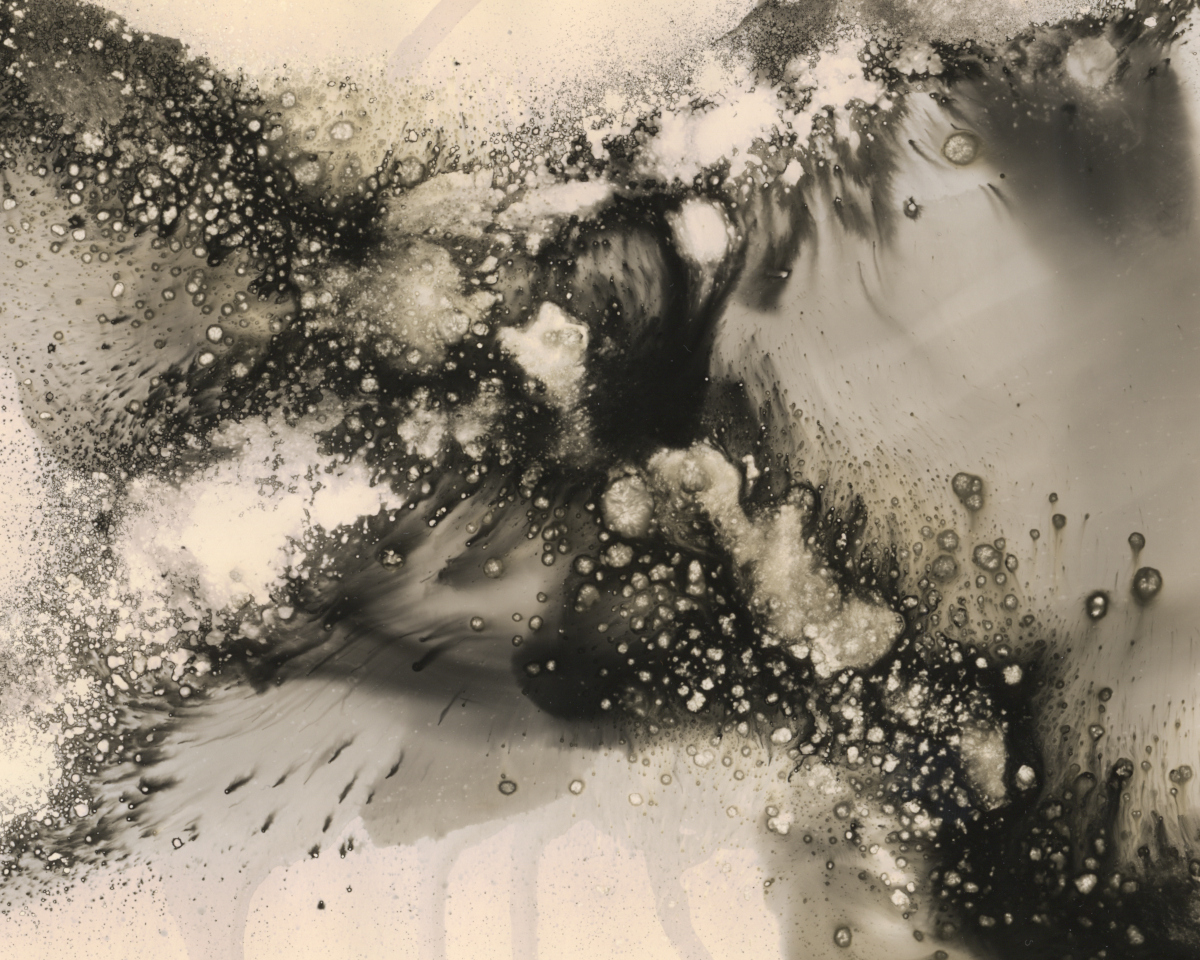
The result was thus incredibly pleasing image of the moon, which I hereafter title “Moon through a dirty window”

Chemigram caffenol contact printLooking at the results obtained shows that the idea of using caffenol in a chemigram process has great possibilities for image making. On its own it can be semi-controlled to create attractive abstract images, while when combined with a regular B&W printing process it turn an otherwise plain image into an intriguingly textured pleasing artwork. I’m very much looking forward to getting back in the darkroom to further work through the possibilities this offers