Serious astronomical imaging requires an equatorial mount for the camera / telescope, which tracks the rotation of the earth for anywhere between 5 minutes and several hours. Commercially available mount options have a starting price of several hundred pounds and range up to thousands. As a result many amateur astro-photographers choose the DIY option, building what’s commonly known as a “barn door mount“. At their simplest, they consist of two parallel planks of wood hinged at one side, with a threaded rod which is manually turned once a minute to gradually open the hinge at a rate which matches the speed of rotation of the Earth.
They are very simple to build, but the pain point should be clear from the end of the previous sentence – you need to control the dimensions such that one rotation of the threaded rod, causes the hinge to open at precisely the right rate. This isn’t as hard as it sounds for short exposures (10-15 minutes) but as the desired exposure time goes up the errors quickly spiral out of control. Some of the error is caused by construction inaccuracies but the bigger part is due to the inherent design decision to produce angular motion (opening hinge) from linear motion (rotating threaded rod). The latter is commonly referred to as the tangent error.
There are various more complicated barn door designs which use 3 pieces of wood to eliminate the tangent errors. Sadly the more complicated designs also increase the mechanical errors due to construction inaccuracies. The easy solution to this problem is to use a programmable microcontroller to drive the mount, allowing arbitrary errors to be corrected in software. When you need a cheap, low power microcontroller, the first option that comes to mind is an Arduino. A little bit of searching on google revealed someone who had built a barn door controlled by an Arduino Uno and a stepper motor. Even better, they provided a sketch of their circuit diagram for wiring it up.
Cost being king, I headed over to eBay to source the big ticket parts, and a maplin store for a few odds & ends I wanted to see in person before purchase. On the list were
- Arduino Uno R3 (clone) : £12.49
- EasyDriver v4.4 : £5.99
- Bi Polar Stepper Motor LDO-42STH47-1684A: £12.00
- SPST Switch ON/OFF/ON : £2.79
- SPST Switch ON/ON : £2.79
- Hard plastic case : £3.49
- 2.1mm x 5.5mm DC jack : £2.09
- 22 guage solid core wire : £2.49
- 1k Ohm resisters x 3 : £1.08
- 5mmx8mm flexible coupling : £0.99
Thus the total cost for the electronics was £46.21, a little bit higher than I was originally hoping for. I could have reduced it by going for one of the lower spec stepper motors which are bundled with a driver circuit board. This would have cut approx £12.00 off the cost, but I was not confident it would have sufficient torque for direct drive of the threaded rod, so I went for the sure bet. A pound or two could have been shaved off the cost of switches / power jack too, by sourcing from eBay instead of maplin. IOW it is probably possible to get the parts for about £30-35 if you really find the bargains. Before assembly the parts are laid out
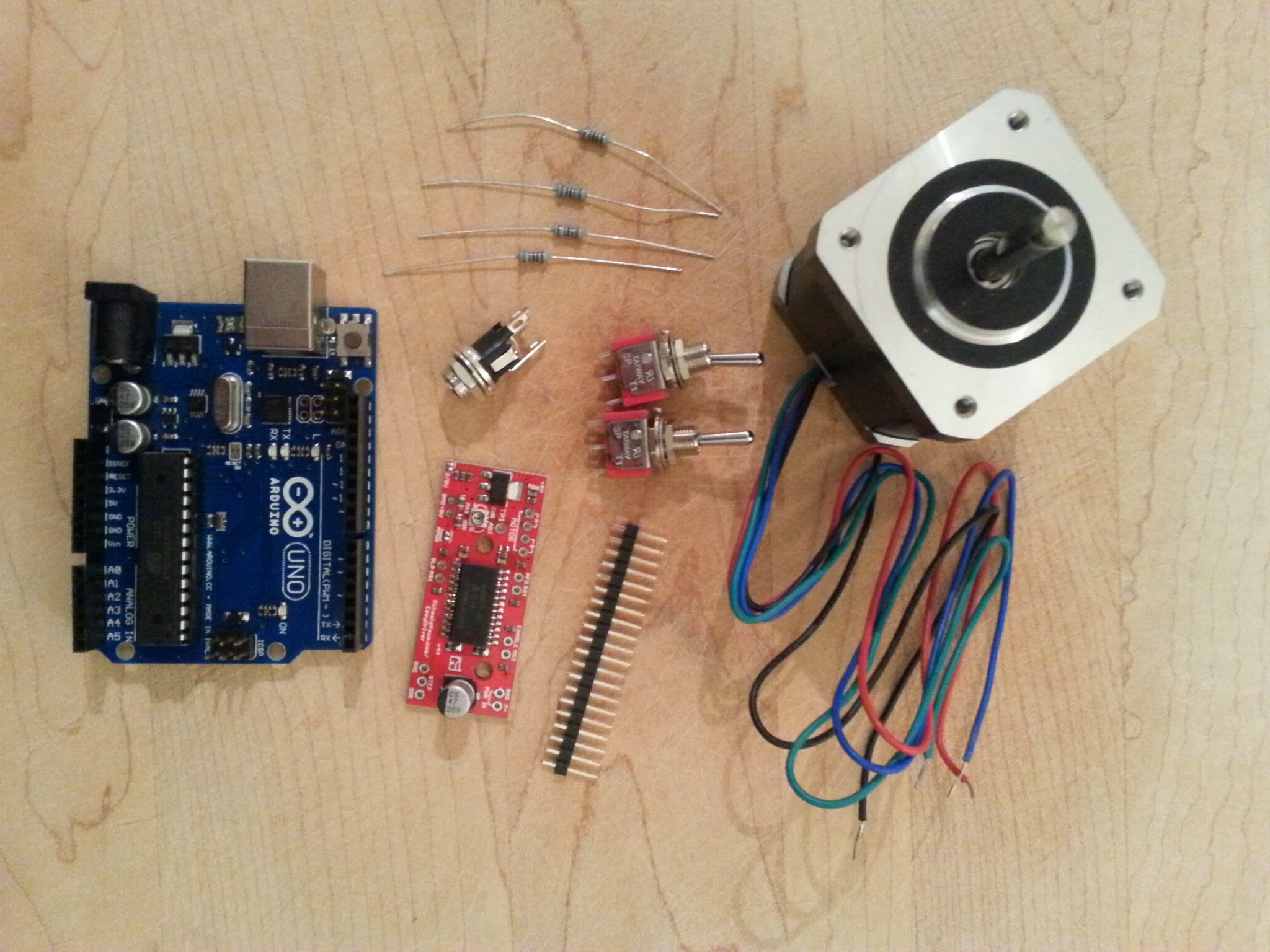
In addition to the project parts, you’ll need a few workshop items including a multi-meter, soldering iron, helping hands, wire cutters/strippers and 3A x 12v regulated bench power supply.
After looking at the previously mentioned circuit diagram, I decided to make one slight variation in the use of switches. I discarded the separate power switch, and used all three prongs from one of the switches to toggle between forward/stopped/backward. Thus the aim was to construct the following circuit diagram from the parts:
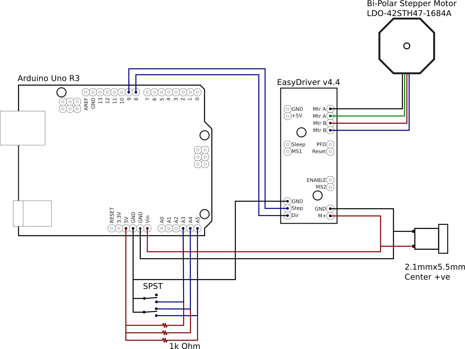
The Arduino is capable of being powered from the USB port, the on board DC jack, or the VIN pin. While the EasyDriver can take a 5v line from the Arduino board, this is only suitable for driving the electronics, not the stepper motor which needs much higher current than the Arduino is capable of supplying. Thus the decision was made to take a 12V supply from a off-board 2.1mmx5mm DC jack, to the VIN pin on the Arduino and M+ pin on the EasyDriver. The DC jack size was chosen to match that used on the Celestron NexStar telescope mounts, and so was wired center-positive.
The EasyDriver needs a minimum of two control signals, one to trigger a motor step and the other to set the direction of rotation. Thus the Step and Dir pins on the EasyDriver board were connected to the digital pins 8 and 9 on the Arduino. The EasyDriver defaults to 8-point microstepping. If use of full steps were required, the MS1 and MS2 pins could be connected to further digital pins on the Arduino. For the barn door mount though, the rate of rotation is so slow that 8-point microstepping is more than OK.
The two switches are going to be used to provide control parameters to the software running on the Arduino. The ON/OFF/ON switch is going to be used to switch the motion of the motor between clockwise, stopped and anti-clockwise. The ON/ON switch is going to be used to switch between automatic sidereal matched speed control and manual fast speed. For wiring, we effectively have a 1K Ohm resistor between the 5V output pin and an analogue pin. The switch is used to short this link out to ground. Toggling the switch thus toggles the analogue pin high/low.
The final piece of wiring is connecting the stepper motor wires to the EasyDriver. The ordering of the wires is absolutely critical. The stepper motor has two separate coils / phases, and 4 coloured wires coming out of it. Each pair of wires corresponds to one of the phases. The key is determining which wires match which phase and the polarity. Fortunately the stepper motor had a model number on it, allowing the data sheet to be located via google. The data sheet shows that one phase is connected to the black + green wires, while the other phase is connected to the red + blue wires. So the EasyDriver motor pins are wired up in the order black, green, red, blue. Again, this order is absolutely critical to get right – mixing up the polarity between the two coils will result in a motor which won’t turn. Likewise, not matching up wires within a phase will result in a motor which won’t turn. It is also NOT SAFE to use trial and error to test the motor while the EasyDriver is active. Detaching the motor wires while the EasyDriver is active will likely result in a burnt-out EasyDriver. Find the data sheet and get it right first time.
After a hour or two cutting and soldering wires the circuit was complete. To test it requires creation of a simple test program in the Arduino IDE. For this test I’d used the AccelStepper library instead of the Stepper library that is normally used, because the AccelStepper is more flexible to use.
#include <AccelStepper.h>

int debug = 0;

int dgPinStep = 8;
int dgPinDirection = 9;

int anPinForeward = 4;
int anPinBackward = 5;
int anPinSpeed = 3;

AccelStepper stepper(AccelStepper::DRIVER, dgPinStep, dgPinDirection);

void setup() {
  pinMode(anPinForeward,  OUTPUT);
  pinMode(anPinBackward,  OUTPUT);
  pinMode(anPinSpeed,  OUTPUT);

  stepper.setMaxSpeed(3000);

  if (debug) {
    Serial.begin(9600);
  }
}

void loop() {
  int valForeward = analogRead(anPinForeward);
  int valBackward = analogRead(anPinBackward);
  int valSpeed = analogRead(anPinSpeed);
  int run = 0;

  if (debug) {
    Serial.print("Foreward: ");
    Serial.print(valForeward);
    Serial.print(" Backward: ");
    Serial.print(valBackward);
    Serial.print(" Speed: ");
    Serial.println(valSpeed);
  }
  if (valForeward < 5) {
    if (valSpeed < 5) {
      stepper.setSpeed(200);
    } else {
      stepper.setSpeed(2000);
    }
    run = 1;
  } else if (valBackward < 5) {
    if (valSpeed < 5) {
      stepper.setSpeed(-200);
    } else {
      stepper.setSpeed(-2000);
    }
    run = 1;
  } else {
    run = 0;
  }

  if (run) {
    stepper.runSpeed();
  } else {
    stepper.stop();
  }
}
After compiling and uploading to the Arduino over USB, the program will start running immediately. If you’re not confident that the switch pins are connected in the right order the “debug” variable can be set to 1, which will let you watch the levels via the IDE’s serial console as the switches are toggled. Just remember to turn off debugging again afterwards because the println calls seriously slow down the program to the point that it is unusable in the real world. The video shows toggling the motion switch between forward/off/backward and the speed switch between slow/fast (sidereal rate is not implemented in the test program)
With everything working, all the remains is to house it in the plastic case. This required drilling a few holes for the switches and DC hack, and carving out a hole with a file for the USB port and carving a channel for the motor wires. With the electronics complete, the next phases are to build the mechanical side of the mount and then do the maths calculations and software programming necessary to track the earth’s rotation accurately. These will follow as separate blog posts in the coming days or weeks.
Now read: part 2, calculating mount movements
Hi,
I am a retired electro-optical and controls systems design engineer having also served an apprenticeship as an optical instrument maker in the early 60’s.
I have just been reading your blog but am left wondering why you have built-in errors due to the drive system you are using when you could use the much simpler and very much more accurate expedient of simply curving the drive screw and mounting the drive nut in the final reduction gear. That way, the dive is always tangential and, therefore, invariable. With a large enough radius a 6mm diameter x 1mm pitch stainless steel screwed rod or threaded bar (nomenclature varies with geography) will be much more accurate than what you are able to achieve with the straight screw.
Some of the helicopter main rotor gears have a nice hex hole in the middle or the drive-nut.
using a radius of 300mm for the rod we get 1884.955 592mm for the cirumference. 1 second of time represents 15 seconds of arc. So, if we divide the circumference by the number of units of 15″ arc, i.e.
1884.955592/360x60x4 we get the velocity of the screw which is 0.021 816 615 mm/s (solar)
1 solar day is 1.002 737 909 351 siderial days so the speed must be increased by this amount thus:
0.021 816 615 x 1.002 737 909 351 = 0.021 876 346 mm/s
If we use a wheel with 50 teeth driven by a 1-start worm this gives 50:1 reduction. If the motor is a 200 step per rev motor driven in half-step mode then the total ratio of steps per rev at the nut is 20000 and this is also the number of steps per mm which can also be written as 0.000 05 mm per step.
What we need is the number of steps per second to give the siderial rate. All we need to do is divide
0.021 876 346 mm per second by 0.000 05 mm per step to yield 437.526 938 steps per second (Hz)
or one step every 2.855 736 ms.
Bending the M6 x 1 screw can be done over a suitable mandrel and does not have to be absolutely accurate as long as it is driven at the 300mm radius from the hinge centreline.
If you take a modern camera, e.g. the Samsung NX with 20MPixels, 23.5mm x 15.7mm (3:2) sensor which is around 5417 x 3678: 4.2micron square pixels. The angle subtended at a pixel varies with focal length thus:
for a 50mm fl lens we have 0.06″ per pixel, a 200mm fl lens gives 0.23″ per pixel and a 600mm fl lens yields 0.68″ per pixel.
Please forgive me if I have given offense as that was not my intention. I used a similar technique a number of years ago on a textile machine that require an accurate circular arc of movement and when I saw your blog I was minded of it. I am sure that all the bits are available and it has just occured to me that there are small brass nuts in rubber that are used on glass reinforced fibre bodywork such as caravans for fastening light units on – much like a sheet metal “riv-nut”. I have also just realised that I am enthused by the article to the point of trying to make a mount myself – tubular hinge with pole finder telescope.
I don’t know how old you are but I am nearing 70 and have done a lot of engineering in a number of disciplines. I can tell you that not much is new and it is always better to find an easier and simpler way to solve a problem if at all possible. I would be minded to make a simple oscillator with a phase locked loop (PLL) and divider so that you could simply alter the feedback ratio to tune the frequency rather than build a microcontroller for the same job. Both systems, ultimately, rely on a crystal for timing and frequency control but PLL would be simpler. If you had other functions in mind then use the controller for that and leave the timing to a dedicated circuit (it could still be controlled by the micro but the software overhead would be much reduced).
Finally, there are aquite a number of dedicated circuits for driving bi-polar stepper motors such as the L297 – phase winding sequencer chip and the L298- current chopper phase driver chip, These are classic IC’s that are used to drive high performance, 2-phase, bipolar wound, stepper motors in both full and hal-step modes and have enable, direction and step inputs that can be controlled by outputs from microcontrollers or PLC’ etc. The 200 steps/rev (1.8deg) biplor wound stepper motors are very efficient and can be very powerful although, in this application, a size 17 (1 3/4″ square) motor from an older 3.5″ HDD would have many times the power needed to track with this device even whn carrying, say, a 600mm F4 lens on an DSLR. For a more reasonable load such as a 200mm F1:3.5 or 300mm F1:4 or 5.6 it would be perfect and could be driven well below its maximum capabilities and would last indefinitely.
I do hope I’ve not bored you to death and would be happy to hear from you as you have now got me thinking!!!
Kind regards,
John
Leeds, West Yorkshire, U.K.
Yes, you are of course right that using a curved rod would effectively eliminate the tracking error in the mechanical design. Use of a curved rod is quite a popular option taken by people building barndoor trackers on the web. There are a two main reasons why I decided to take the approach I did.
Firstly, I’m a software engineer by profession, and this is the first time I’ve done any physical construction projects since I was at school many years ago. I was not entirely confident that I could do a good enough job on the mechanical construction to fully eliminate the tracking error even with a curved rod, since the length of the hinge-to-pivot distance and curvature of the rod have to be pretty accurate. If I go for the simpler mechanical design though, I am fully confident in my skills to correct any tracking errors through software. IOW the decision I made was to play to my strengths.
Secondly, I’ve been wanting to learn & experiment with either the Raspberry Pi and/or Arduino microcontroller boards for a while, and this project offered the perfect opportunity to do so. So even though using a microcontroller + custom sofrware it is arguably overkill for this project, it was none the less something that I wanted to do purely for my own interest.
One of the nice things about doing a home-brew barndoor mount is that there are a thousand and one different ways to construct the thing, so you can try out your own ideas and satisfy your own interests, and still come out with a decent end result.
I too am a retired engineer, 67 years old. As for complexity of design, I agree that simpler is better if it achieves the desired results, and a simple barn door servo driven mount as documented in various articles will suffice. However, that does not advance the technology. I applaud the author for thinking about how to take this to the next level, by using a microcontroller instead of a bent rod. The author should not be discouraged by “simpler is better” but should be challenged to make it better, not just simpler. We already have simple, now make it better. Throughout my career one of the things that has differentiated me from my peers is to not be afraid of new technology and ideas. The engineers who held on to old proven ways of doing things got the maintenance projects, while I got the innovative projects.
Thank you for your very detailed and well written tutorial. Inspired by this tutorial, I wanted to build a arduino driven barndoor, too. I have a question regarding your easydriver and stepper motor configuration. The stepper i am using has a very similar spec to yours, my current per phase is given with 1.6A. To which value did you set the current limit of your easy driver, because the easyriver can only supply max 750mA?
Yes, the motor I used was ~1.6A/phase too. I did not change anything related to current limits on the easydriver though. IIUC, the fact that the easydriver only supplies 750mA merely means that the motor won’t be driven to its full design torque. The reduced torque is not a problem for the barndoor application since the motor isn’t under any kind of high torque load. I think there was a FAQ item on the EasyDriver website about this somewhere, but can’t find it right now
Daniel,
Thanks for this great tutorial. Did you ever get any photos using the barn door you built? I have been working on a barn door myself for the last month or so and plan on using it with my 4×5 camera. I have tried several approaches using the Arduino as the controller for an isosceles barn door drive. For some reason, even with your approach I do not seem to be getting the correct tracking. After one hour of operation, I do not get the ~15 degrees of opening.
Now I am not using the EasyDriver stepper driver. I am using an L298 driver and allowing the arduino to step through the 4 pins. I am using AccelStepper and made mods to your code to account for this in setting up AccelStepper and then in setup() for inverting the pins. I also set it up to step in Half Step mode and set MICRO_STEPS to 1. I seem to be tracking at 1/3 to about 1/2 the necessary speed.
Any thoughts?
Youssef
Hi there, I have built an aluminium barn door tracker with a curved rod design. Using an M8 X 1.25 pitch brass screw. I am an engineer by trade so ive managed all this. I found a calculator online to work out the radius of the curved rod. Then im running that on a 64 tooth gear on a bearing which the curved rod runs through, then onto a 16 tooth gear which is of course on the stepper motor. Therefore to get 1rpm I need my stepper motor to turn at 4rpm. Now, I have used your guide for the electronics side of things. I have ordered exactly all the things you mention above and intend to wire it up exactly the same. My problem arises because I am a total newb when it comes to programming the controller! So please tell me, will I be able to just use the code on page one of your design for my build? But more importantly what changes to the Stepper speed do I have to make to get my desired result? You have set:
stepper.setSpeed(200);
What number will be the ideal for me instead of 200? I have tried to find this answer elsewhere and am at a bit of a loose end with it.
The rewind speed of 2000 looks ideal so I will keep that for rewinding!
Any help from you would be massively appreciated! I can never thank bloggers like you enough for your detailed guides! You make it possible for others to enjoy great projects like this, so thank you in advance!
Kind Regards
Ryan
I don’t think that the code I have written will work with a curved rod. The mathematics I describe in the later parts of this blog series are calculated based on the way a linear rod creates rotational motion in the barndoor arms. Specifically we need to gradually increase the speed of turning as the barndoor opens further. I’ve never investigated the mathematics for a curved rod in detail, but I’m fairly sure I recall that the way curved rod opens the mount will have different rules, and would thus require different logic in the arduino software. If anything the logic for a curved rod should actually be simpler, since IIRC the whole point of bending the rod is that it can then be turned at a constant rate. ie no need to adjust the rate as the barndoor opens like you need with a straight rod.
If I’m right that a curved rod needs a simple fixed rate, then you can basically cut out all the fancy maths from the software and just set a fixed speed.
Hi, firstly thank you for your reply. Yes I assumed my build would require a set fixed speed. I thought this is how your simple test program was programmed and all I would have to do is edit the speed? Im talking about your initial test program that you made the youtube video above with. Is that turning at a fixed rpm?
Thanks
Ryan
Ah yes, I didn’t realize you were referring to this first demo/test program. That does indeed turn at a constant speed. The number 200 was just plucked out of thin air – it has no maths behind it. The key thing you’ll need to figure out is how many steps are required in order to complete one 360 deg revolution of the threaded rod. From the dimensions of your barndoor mount you should know how many revolutions are required per minute, so then just set the speed based on steps per minute.
Hallo Ryan,
Do you have drawings of THE aluminium barndoor?
Kind Regards,
Raduen
What is your power source in this design, both in your initial testing and final design, it looked like in part 5 you have a car cigarette plug. Also, my understanding (albeit extremely limited) was that the Easy Driver required +5v to power the logic board separate from the 6-30v PWR IN, is that only necessary for micro-stepping? I really appreciate this write-up, I love astrophotography but I’ve been rather hamstrung without an equatorial mount.
I use a 12v Tracer Lithium-Polymer battery which I already had for my main telescope. They are awesome batteries due to their small size and weight, but any reasonably powerful 12v supply ought to do.
The Easy Driver has two sets of power inputs and only one needs to be used. It can take a regulated 5v input and work everything from that, however, the arduino 5v output cannot provide enough amps to use this. Thus my wiring uses the M+ voltage input pin which accepts anything 7v -> 30v and use a built-in regulator on the board to step it down to 5v to drive the board and the motor.
Great set of articles!
I have a 12VDC 1.5A plugpack that i can plug into my uno using the power jack. you say the 5v output pin on the uno wont supply enough amps so does this mean i cannot use the power pack i have or can i alter it in any way to directly wire it to the easy driver and uno?
Sorry the power side of things confuses me a fair bit and i don’t want to destroy anything or do anything dangerous!
You have two circuit boards which need a power supply – the arduino uno board, and the easydriver board. The Uno has both power supply input pins and power supply output pins. The power supply output pins on the Uno can in theory be used to power other circuit boards, like the easydriver. The uno output pins, however, cannot supply enough current for the easydriver to work properly. So you must directly power the uno and easydriver boards, via their respective input pins, from your power supply pack.
Hi.
I’ve started following the instructions and I’m in the process of testing the stepper motor.
I noticed on the drawing you’ve got the direction pin as 8 but in the code it’s 9.
(Just thought I’d point it out as it threw me for a little while)
And I thought this article was about a “Diy Barn Door” project. LOL, I ended up reading all of it any way and learned some things, thanks.
HI,
I’m late to the party on this an I have been looking at a variety of barn door mounts. All that I have found use a version of the threaded rod, either with a curved rod or like yours with swivels to cut down on the errors.
I am wondering what stops you from mounting the motor axially with the hinge and operating it that way. Of course the load would possibly be higher depending on the camera mounted but with a direct drive one would just need to set motor rotation to sidereal rate and be done with it. No need for fancy law of COSINES.
I am about to embark on a barn door tracker. I have curved plans, which simply need driving at 1 rpm and apparently it is quite accurate. However, I am thinking about making my new design from stainless box section and bearings etc to be absolutely “cock on” engineering wise.
I was looking at a way to drive it that was accurate, to enable proper long exposures. However, I know nothing about electronics. Please could you help?
I would be willing to make two “actual mounts”, for the assistance.
Hi, I don’t know if this thread is still open, but…I’ve built this barndoor design. I did it in wood first, and then a completely 3D-printed version for higher precision. Both times I’ve had the same problem: the pivoting panels slightly move up and down (and slightly also rotationally right-left), leading to a periodic error, which is evident when shooting at 200mm. Did anyone have the same problem and found a way to solve it? Thanks!
Is there any way I can just pay to get one of these already built? I am someone with too much ADHD to focus on making this without it being left unfinished. Any advice would be apreciated.