In part 1 of this series, I described how to construct an Arduino based motor controller. This time around it is time to look at the mathematics behind the movement of the mount. As noted previously, the mount will be driven by a threaded rod. As the motor rotates the rod in a nut attached to the camera board, it generates linear motion, however, the board needs to open up with constant angular motion. For simplicity it is intended to construct a type 1 barndoor mount with an isosceles drive rod, as illustrated in the following diagram
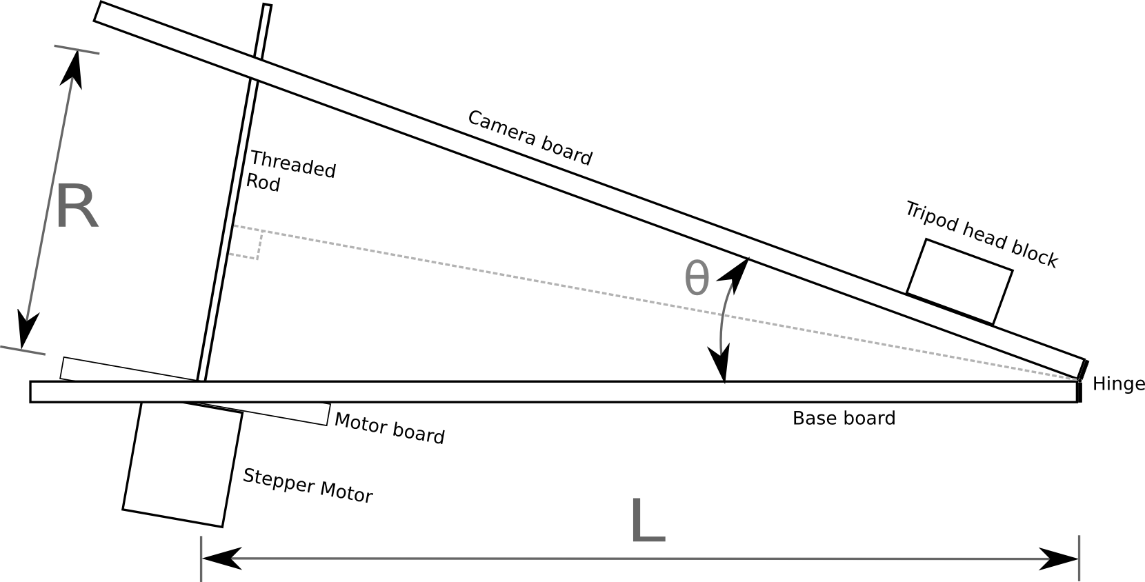
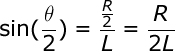
In the above diagram the threaded rod has length R between the two boards, forming an angle θ. It can readily be seen from the diagram that the isosceles triangle formed by the two boards and the rod can be split into a pair of identical right angle triangles. Basic trigonometry tells us that the sine of the principal angle in a right angle triangle is equal to the ratio between the opposite and hypotenuse:
![]()
In our diagram above, the principal angle is θ/2, the length of the opposite is R/2 and the hypotenuse is L. Plugging those symbols into the first formula we get:
In order to drive the threaded rod, the value we want to calculate is R, so we need to re-arrange the formula to get R on the left hand side:
![]()
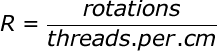
The Arduino isn’t directly controlling the length of the rod though, rather it is controlling its rotation. The length of the rod is the ratio between the number of rotations and the number of threads per centimetre. This gives us a second formula for R
Lets substitute this new formula for R, into the previous formula:
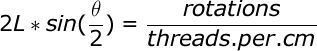
A few moments ago we mentioned that the quantity we actually control is the rotation of the rod, so the formula must be re-arranged to get the number of rotations on the right hand side:
![]()
With this formula, we know how many rotations are needed to achieve a given angle between the boards, but what exactly is the angle we need ? The Earth doesn’t take exactly 24 hours to rotate a full 360 degrees, in fact it is about 23 hours, 56 minutes, 4.0916 seconds. This value is known as the sidereal time or rate. With this information we can now define a formula to derive the value for θ at any given time t, since starting operation of the mount from a closed position:
![]()
Since θ is the value we need, lets re-arrange that formula to get θ on the right hand side
![]()
This formula for θ can now be substituted into the earlier formula for calculating the rotations of the rod:
![]()
The final term can be slightly simplified by removing a factor of 2
![]()
This formula operates in degrees, but when doing calculations in software it is desirable to measure angles in radians. There is a simple formula for converting from degrees to radians:
![]()
With this information it is now possible to update the formula for calculating rotations to operate in radians by substituting in the conversion formula:
![]()
A little while ago it was said that the Arduino is controlling the number of rotations of rod. This isn’t strictly true, it is in fact controlling the number of steps of the motor. A motor will have a certain number of steps it can do in one rotation, which gives a step size in degrees. The formula for calculating rotations can thus be adapted to calculate the number of steps

This is our last formula and it has 4 variables to be filled in with accurate values
- stepsize: the stepper motor used in the electronics does 200 steps per rotation giving a step size of 1.8. This is a common size for this type of stepper motor. Another typical size is 64 steps per rotation.
- threads.per.cm: a standard M8 threaded rod will have 10 threads per centimetre, other rods may vary.
- L: this is the length of the base board between the hinge and the centre of the threaded rod. This has to be precisely measured after construction is complete
- siderealtime: 23 hours, 56 minutes, 4.0916 seconds, or more simply 86164.0419 seconds
This formula could be executed directly on the Arduino board, but a sine calculation is somewhat heavy for the microcontroller. Realistically the mount isn’t going to be doing exposures of longer than 2-3 hours. It is fairly trivial to thus this formula and calculate the required number of rotations for each minute of each hours and produce a 180 entry table. The Arduino then merely has to keep track of time and do a trivial table lookup to determine the rotation rate. An algorithm for doing this will be the subject of a later blog post.
Now read: part 3, drive control software
Excellent. I’m looking forward to the rest of this series. I’ve been looking for a good arduino project for a while, and also looking into a tracking mount for my camera, this project would suit both perfectly. Thanks for posting such comprehensive articles on it, much appreciated.
Great! Your two posts are really excellent, congratulations for them. They will allow me to build a motorized Scotch mount for astrophotography. I wait for the next posts.
I was wondering if you had developed the code for the sidereal ramping yet? I’m planning on doing the exact same thing, except with a curved leadscrew and a gear reduction drive attached to a stepper motor. I may just build a scotch mount, but this seems like just as good of a solution to me.
I’ve not done the arduino code yet – that is my project for this coming weekend. I don’t expect it would be hard to adapt for a curved rod since an (accurately) curved rod with accurately constructed wood mounts would simplify the maths. I’ll try to point the final parts of this blog within in the next week including any code under GPLv2+
Are you going to include details of the mechanical construction in the next parts? The software i’m happy with, however i’d love to see exactly how you construct your tracker and where you source your parts etc. I’m also planning a curved screw to simplify the tracking code and to simplify construction itself, removing the need for pivoted mounting of the scew/motor etc.
I will eventually be posting an article with the construction details. Real life has temporarily got in the way of this project. A curved rod could simplify the maths, assuming your construction skills do a good job at making the right bend in the rod
I’m using the info from this project as well. Interestingly enough, there is not very much info on how to make a stepper rotate constantly at a precisely set speed with the Uno. Most of the circuit descriptions I have found are about how to move from point A to point B. Thanks, but I already have 2 CNC robots, and a barndoor needs something else! Thanks for sharing!
Jim
Thanks for the awesome derivation. It saved my life. Only one question.
What is the unit of L, centimeters or millimeters?
Abhishek
The key is to keep the units consistent throughout. Since we’re measuring the rod using “threads per cm” then the value of L must also be using cm.
hi
I’m building similar project. I saw the video on youtube. But I think the speed of stepper motor will no be too fast?
luca
The video is just demonstrating the operation of the electronics. In real world use the speed of the stepper motor will be much much slower than what the video shows.
Hi Daniel,
How’s the next part coming along? Don’t keep us all hanging :)
Thanks
I have built the mechanical parts now, but real life has got in the way of writing up the details of that. I will get around to it soon I hope
Nice project. I hope there will be an update soon. Looking forward to rebuilt it. About half of the stuff is lying around here.
How cool is this! im actually trying the same project at the moment, but i’m still learning how to program the arduino correctly. So far i only managed to rotate the stepper motor at a certain speed and direction. I’m looking forward to the rest of your updates!
Douwe
If anyone wants a sneak preview of future parts, I’ve uploaded the arduino source code. I’ll be explaining it in detail in later blog post https://gitorious.org/fstop138/barndoor/
Still looking forward to the next updates – hopefully soon!
Count me in as another one who’s looking forward to the next update!
After a longer delay than anticipated I’ve now published part 3, drive control software. Parts 4 and 5 focus on mechanical construction will follow very shortly….
Part 4, construction diagrams is now published.
And finally part 5, photos of the finished device.
Hi have been reading your blog with eat intrest, and as an enthusiastic amature photograper wantind to get better night sky images this looks like a great solution. I have an arduino to play with and this looks like a great project.
So my question is being new to the coding.. you mention using a 180 look up table to help with calculation, and this will be discussed in a later blog post?( see below)
Is this already included in the code you have put at Gitlab??
regards
Bryn
This formula could be executed directly on the Arduino board, but a sine calculation is somewhat heavy for the microcontroller. Realistically the mount isn’t going to be doing exposures of longer than 2-3 hours. It is fairly trivial to thus this formula and calculate the required number of rotations for each minute of each hours and produce a 180 entry table. The Arduino then merely has to keep track of time and do a trivial table lookup to determine the rotation rate. An algorithm for doing this will be the subject of a later blog post.
I didn’t need to use any lookup table in the end. It was easily fast enough to calculate on the fly on the arduino.
As theta increases, L decreases since the pivot points are not on the inner surfaces of the boards.
If P is the distance from the surface of the board to the pivot points (and is the same for both pivots), and M is the decrease in L, then
M = P * tan(theta/2), and L(theta) = L(0) – P * tan(theta/2). This can be plugged into your final formula. For small angles it is obviously negligible, but my calculations show an accumulated error of almost 1 degree of arc over two hours with L = 300mm and P = 30mm.
Cool, I knew the position of pivot points would cause some error, but never had time to look at the maths to see what correction could be made in software. Thanks for pointing out the mathematical solution to correct the errors !
Just a thought but wouldn’t it be a LOT simpler to calculate the circumference in millimetres that the barn door would theoretically turn around (2L times Pi) and divide 86164 (the sidereal day) by that to get the number of seconds per thread or revolution? Then divide by 200 to get the time per step?
HI Daniel,
I have built everything in your write exactly to specs, and have tested the controls using the test code, everything works exactly when i use the test code. but when i upload the final comment from gitlab nothing happens as far as motor movement, nothing. im not sure if im including the library’s wrong but i have tried absolutely everything i can think of. im not sure if you still pay attention to this blog but your help would be greatly appreciated. Also i get no errors when checking before upload.
Best advice would be to double check & triple check the pins used for the wiring between the easydriver & arduino, and between the arduino and the switches. If you have connected to the wrong pins, then the code will not be controlling the things in the right way. If you find a mistake either re-connect to the right pins, or more easily, just change the code to look at the pins you actually used.
Thanks so much for replying, i guess i had tunnel vision and just by you saying that made me check everything. I had it wired for the test comment but in the final comment the step and dir are swapped and that all it was. thanks for the project it was a fun one!
One thing I think may be in error on an otherwise great derivation: you seem to be using threads per cm as a proxy for thread PITCH. The rod I’m using for example is for a 3D printer kit; it has 5 threads per centimeter, but a pitch of 8mm, that is, each full rotation causes 8mm of travel of the nut; this does not necessarily have anything to do with thread count. Using the equation R = #rotations/thread count, we end up with a mismatch because R is a distance in cm, not a unit of threads/rev. If we instead say that R = #revolutions/pitch, we end up with cm = revs/(cm/rev) which reduces to R = cm. This also jives with my previous comment on the code page that using a value of thread count = 5 in the table of variables causes the tracking setting to run much too fast; I’ve timed it to be ~35-40 degrees in 30 minutes instead of 2 hours; this is about the same factor in time-to-angle as the factor between .8 and 5.
I believe you are correct in your analysis. I was lucky in my original work in that the threaded rod I was using had 10 threads per cm, so my mis-interpretation had no ill effects. If you want to send a pull request to fix the source code, I’d be happy to review it & update this article to account.
Thank you, that sounds great, and thank you for your fast reply. I went back through the derivations and I believe that the proper units here are not pitch but actually inverse pitch, that is, how many rotations are required to yield one full cm of travel along the rod. For my example, this would actually be 1.2 (at a pitch of 8mm, it takes 1.2 revs to travel 1cm).
I inserted a value of 1.2 into the value table for the THREADS_PER_CM variable, reflashed the Arduino, and taped a protractor to the side of my barndoor with the center at the hinge pivot. After timing it for an hour in “Track” mode it got to ~19 degrees, exactly what I would expect given that the start angle on my particular setup is 3.77 degrees due to the coupler offset above the motor panel.
For some reason I wasn’t able to do a full pull request, but was able to log an issue over at Gitlab.