In recent months I’ve had an increasing interest in astronomy and astrophotography, to my surprise discovering the Baker Street Irregular Astronomers who hold monthly observing sessions in Regent’s Park – I never imagined it was practical todo astronomy in London’s light polluted sky. I’ve not got as far as purchasing a telescope yet, instead deciding to learn a bit more about the topic first, and experiment to see what I can do with just a DSLR camera. With a Nikkor 180mm prime lens and 2x teleconvertor I was able to produce this image of the Moon
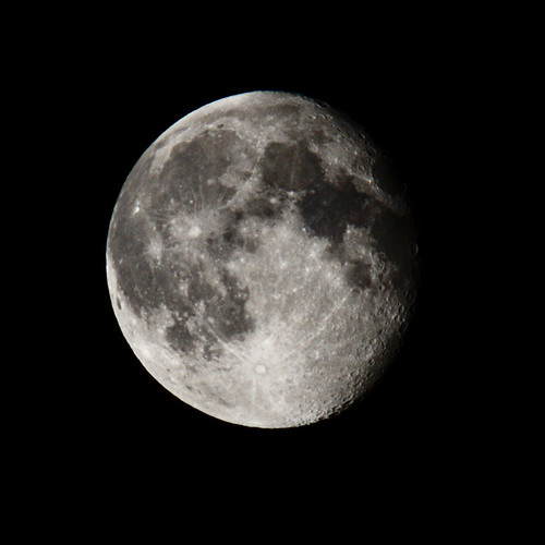
The Moon
The 180mm lens + 2x teleconvertor on the D90’s 1.5 crop factor sensor gives an full frame equivalent of 540mm. This is really the bare minimum acceptable reach for getting images of the moon, with the image above being a pretty aggressive crop down. There are enough pixels for publishing online, but not really sufficient for printing out at any reasonable resolution.
As most people know, by a stroke of good fortune, the Sun and the Moon have the same apparent size when viewed from the Earth (this is how the moon can precisely block out the Sun during an eclipse). Naturally, since I was able to get a nice image of the Moon with the setup described above, I could expect to get a similar sized image of the Sun. Of course looking at, or pointing your camera at, the Sun is an incredibly dangerous thing to do. You absolutely must take care to protect both the camera optics and your eyes if you are going to try solar imaging. There are a variety of solar filters available in the astronomy market with varying characteristics, but for basic full spectrum DSLR imaging, what you want is a filter built with a piece of Baader AstroSolar Safety Film. This is available in A4 sheets from any decent astronomy store, in my case The Widescreen Center, near Baker St.
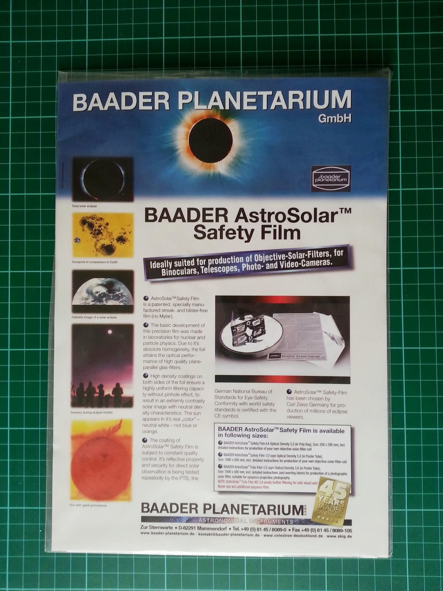
Baader AstroSolar Safety Film
The pack just contains one fine sheet of film, around which you need to built a mount to hold it in place in front of the lens. This involves a bit of fun with cardboard, scissors, sellotape and a craft knife. The mount will consist of two flat pieces of card with discs cut out to sandwich the film between, and a tube that will fit snugly around the lens barrel. The basic cut out shapes used to construct the mount can be seen in the image below:
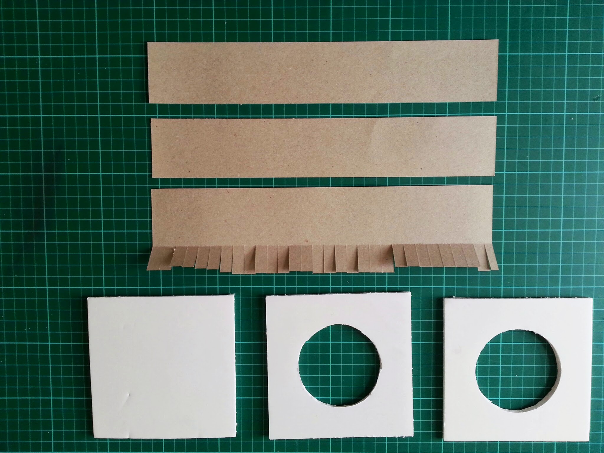
The cut-out parts
For the front sandwich I decided to use 4mm poster board to get rigidity. The centre cut outs are just a few mm smaller than the lens diameter ensuring the lens front will not be pressing on the relatively delicate solar film. I decided to cut a 3rd piece to act as a front flap cover to protect the film when not in use too. For the tube, I decided to use thin cardboard – something little thicker / stiffer than than commonly used for cereal packets. The first two strips of it are 2 inches wide, while the third has an extra 3/4 of an inch, which is then cut into a series of little flaps. These flaps will be used to attach the collar to the front sandwich.
The first step was forming the tube / collar around the lens. I placed double sided sticky tape along the two strips of cardboard without the flaps. I fastened the first strip snugly around the lens:

Forming the collar
The next two strips of card simply wrap around the first, reinforcing its shape. Finally the outer layer is wrapped in a strip of black duck tape to secure it fully.
With construction of the tube out of the way, we can move onto construction of the front sandwich. The key thing to remember at this step is that we do not want to place the safety film under tension – it is actually desirable if it is a slightly loose / slack and this will not affect the image quality at all. The Baader instructions recommend laying the film on a sheet of tissue paper to protect it from any roughness on your work surface.

The Safety Film
The film is actually highly reflective & silvery – the yellowish colour seen above is caused by the reflection of light from the walls in my house. The two plasterboard pieces need to have one side each, covered in double sided sticky tape. Gently place one piece face down onto the safety film, lightly pressing around the edges to get good contact. Then flip the board over so the safety film is facing up again and place the second piece of board to complete the sandwich. Now bind the whole lot together by wrapping more tape around all the edges, taking care not to touch the area of film visible through the cut out disc. The 3rd piece of poster board for the protective cover can now also be attached with a few more pieces of tape.
The last stage is to attach the lens collar to the front board, with yet more double sided sticky tape. For added strength, I finished it off by adding strips of duck tape along the join between the collar and front boards. If all went the plan, then the result should look something like this
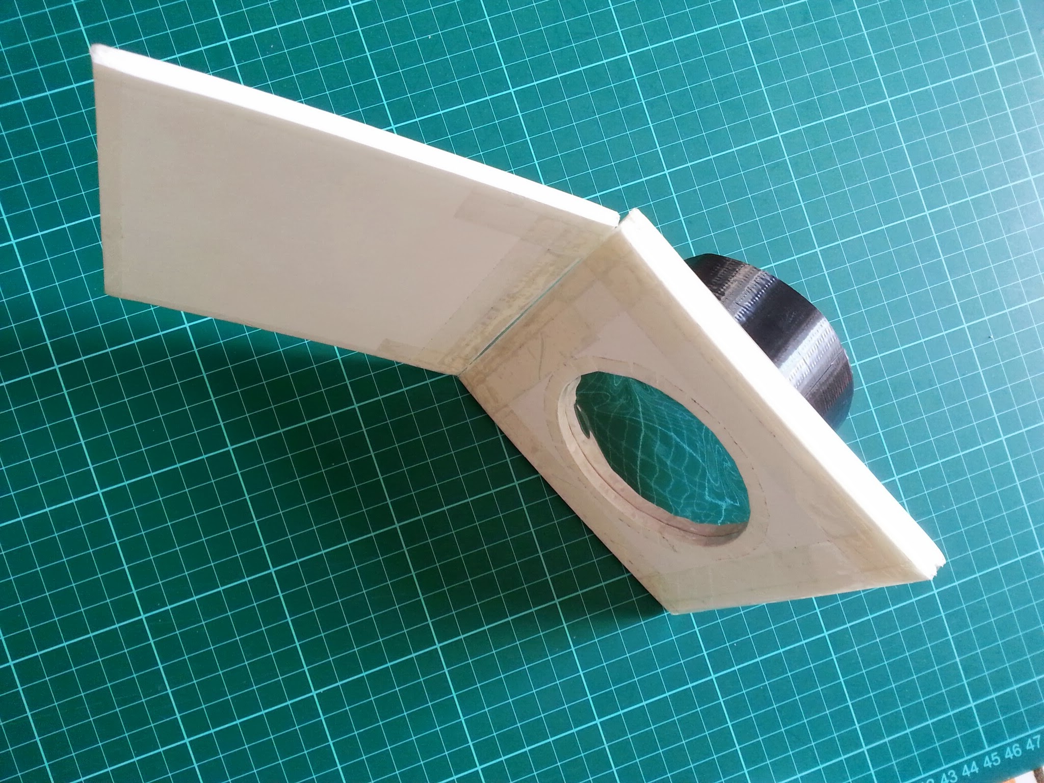
Finished filter
With the camera attached to a tripod, and the filter in place on the front of the lens, the complete setup looks like:

Filter attached to the camera
The weather was looking kind of dicey while I was constructing the filter, with pretty heavy cloud. By the time I had taken a break to eat lunch though, the cloud had cleared enough that the Sun was visible for a few minutes at a time. This allowed an opportunity to try out the newly constructed filter. Before using the filter though, it is essential to verify that the safety film was not damaged during construction. The instructions that come with the film describe the kind of defects to look out for, basically tears, scratches, holes, etc. The check for damage should be repeated again every time you go to use the filter. You cannot be too paranoid when imaging the Sun. For additional safety it is advisable to not directly look through the camera view finder, even when the filter is in place. Instead either use the live view from the LCD screen on the camera, or better yet, tether the camera to a laptop using a USB cable. I chose the latter approach, controlling the camera from a laptop using Entangle.
Actually attempting to take a photo though highlights another challenge – that of lining up the camera so that it points at the Sun, without actually looking at the Sun. To get the initial rough alignment, I adjusted the tripod head so that the camera lens was parallel to one of the tripod legs, then shifted the entire tripod around until the shadow cast by that tripod leg disappeared. With rough alignment achieved, I then enabled “live view” in Entangle and made minor changes to the tripod head until the Sun appeared in the centre of the screen.
Aside from the safety benefit, one of the key reasons to tether the camera to a laptop is that it makes focusing much simpler. The laptop screen can zoom the preview image until it shows pixels at 1-1 size. Very small tweaks of the lens focusing ring can then bring focus into the sweat spot. The result of all this work, was the following image
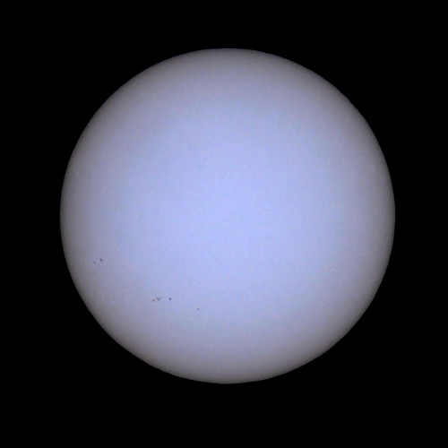
The Sun
Click on the image above to be taken across to flickr where it can be viewed full size. The white colour is the result of the of the Baader film doing its job. If a traditional “yellow” image is desired, it is a simple matter of adding colourization when post-processing the image. The handful of dark smudges in the bottom left quarter of the image are sunspots.
Overall the construction of the filter took somewhere between 1+1/2 and 2 hours (I wasn’t timing it so don’t know the exact time). When viewed with normal full spectrum light, the Sun does not produce anywhere near as interesting an image as the Moon. It was none-the-less satisfying to be able to capture the sunspots. The limiting factor to producing a better image at this point is likely the need to get a longer focal length lens. As mentioned earlier the setup used for this image, was equivalent to about 540mm. If I can switch the Nikkor 180mm lens out for something like the Sigma 150-500mm lens, it would be able to get to 1500mm full frame equivalence. Of course, first I’ll have to buy the Sigma, and then go through the process of building another filter to fit that lens, since its diameter is no doubt different to that of the Nikkor 180mm. Those who really get addicted to solar imaging will end up buying dedicated scopes with Hydrogen-Alpha or Calcium K-Line filters, which produce some really stunning images.