This posting talks about the key equipment needed to do planetary astrophotography on a low budget. For deepsky astrophotography on a budget, a barndoor mount is a better starting place.
One of the first surprises when learning about planetary astrophotography is that you don’t actually want to capture images. Instead, standard practice is to capture videos of the objects in question, a minute or more in length. These are then processed with a variety of applications to produce an image that is far higher in quality than what you could get if you tried to directly capture a still image. So in terms of equipment, what is needed is a telescope and a video camera of some kind.
The Camera (Modification)
There are plenty of video cameras designed explicitly for astrophotography, able to capture either monochrome or full colour images. For a monochrome camera, coloured filters are used to enable separate videos to be recorded for each colour channel. Dedicated astrophotography cameras are at least £100, often much, much more. As a beginner it is hard to know what will be the choice to start with and even whether the interest in astrophotography will stick. The low cost route is to thus go DIY, which involves taking a regular computer webcam and modifying it to make it suitable for astrophotography. There is an enormous selection of USB web cams on sale in the shops, and an even bigger selection second hand on eBay. Some are more suitable for astrophotography than others, so it pays to do a little research on the forums to figure out which have proved effective. Almost every forum thread on the matter will at some point recommend the Philips Toucam, but these are long since discontinued and postings on eBay sell for an unreasonable amount of money.
A little research, suggested that the Microsoft Lifecam Cinema HD is a good contender, and can be had on eBay for as little as £20. This is capable of capturing at a resolution of 1280×720, which is actually higher than many dedicated astrophotography cameras. It is worth pointing out though, that resolution is not king as the individual pixel size, low light sensitivity and noise characteristics all have a huge impact on the end result. The appealing quality of this particular model were the detailed instructions Gary Honis has written about the modifications needed to make it suitable for astrophotography. The images of Jupiter he posted give an indication of what the camera is capable of. Incidentally his website is a fountain of knowledge when it comes to astrophotography camera modifications.
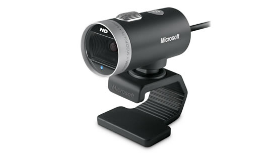
Microsoft Lifecam Cinema HD, as sold
In essence the mod requires stripping off the case to expose the camera assembly and circuit board, followed by very careful surgery to remove the lens and infrared filter, thus exposing the bare CCD chip. Part of the case is then re-attached before fitting it into a 1+1/4″ cylindrical case the same size as a telescope eyepiece. Gary used a pair of eyepiece extension tubes, but the UK company Billet Parts sells a plastic case custom designed & machined for astrophotography mods of the lifecam cinema. If there website shows out of stock just email them and they’ll produce another batch. Highly recommended, as it comes with a dust cap too.
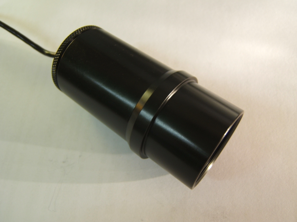
Microsoft Lifecam Cinema HD, modified
One final point is that the CCD chip is sensitive to infrared and the built-in IR filter was removed during the modification. So for doing normal colour imaging of planets, a replacement IR filter will be required. Any standard 1.25″ eyepiece filter can screw into the custom billetparts case, and suitable 1.25″ IR filters can be had for about £20-25 online.
The Capture Phase
With the camera chosen (or built), the first actual step in producing an image is to capture a video. When targetting Jupiter, it is generally recommended that video captures be no more than 2 minutes in length, otherwise features will begin to suffer from motion blur due to its high speed of rotation. If capturing the 3 colour channels separately with a monochrome camera & filters, that means each individual channel is limited to no more than about 40 seconds (and that assumes you have a filter wheel for fast changes). When targetting the Sun or the Moon, it isn’t necessary to worry about rotational speed of the target, so videos can be as long as desired.
For video capture on Linux, the open source program guvcview offers full control over all the camera settings and the video codecs used, which is an important requirement for astrophotography. Maintaining maximum possible detail/quality in the initial video is key to being able to bring out good details in the final image. Critically, transcoding the video from one format to another is to be avoided, as this will usually loose information. The goal is thus to capture in a format that the video stacking application will be able to read directly. The best choice is thus an AVI file, ideally with raw uncompressed codec, or failing that something common like MJPEG. Before going out at night to capture something important, do a quick test capture of 15 seconds and try to load it into the stacking program you intend to use, to verify that it can indeed understand the codec you chose. Using raw uncompressed video results in massive file sizes even for a 60 second capture and may have a lower maximum frame rate; MJPEG is inherently throwing away detail so can compromise the final image quality but allows for higher frame rates. The frame rate is fairly important as the more frames that can be stacked the better the final image will typically be. Pick your poison.
Accurate focusing of the telescope is also a very important factor when capturing the videos. Slight mistakes in focusing can really badly impact the final result. It is worth investing in a focusing aid like a Bahtinov mask for your telescope instead of trying to judge it by eye. While you can make your own, another UK company Morris Engraving produces high quality masks from toughened black acrylic, custom designed for every telescope you’re likely to need, at a very reasonable price on eBay. Again, highly recommended.

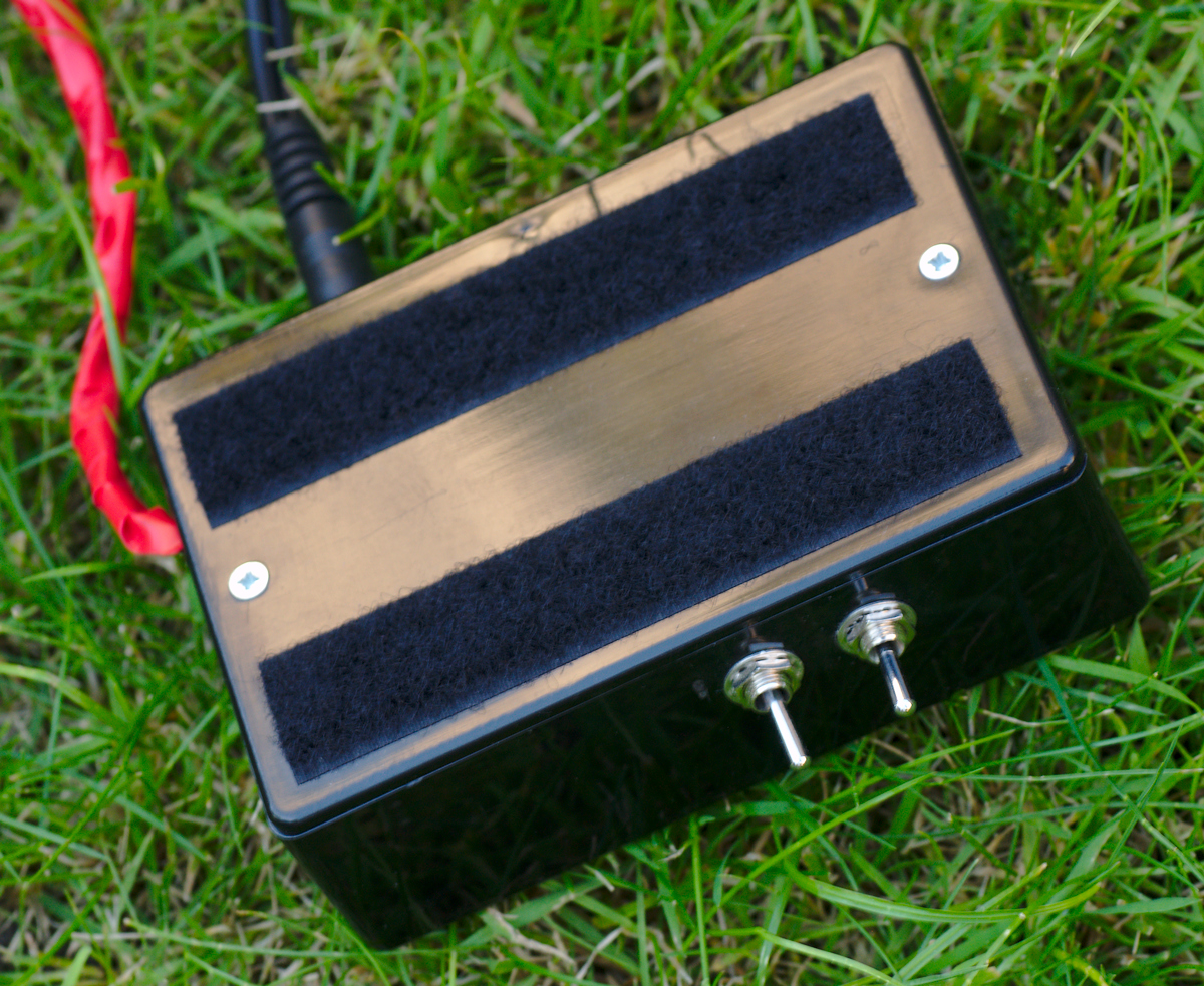
Bahtinov Mask
I am using a Celestron Nexstar 4 GT telescope, which is a Maksutov Cassegrain design with 4″ / 102mm diameter lens and 1398mm focal length, giving approx f/13 aperture. The long focal length is quite good for planetary imaging & observing, but makes it fairly poor choice if deepsky imaging is your plan (a fast refractor is a better choice for deepsky). The equivalent model sells new for about £500, but I got mine second hand from a friend for considerably less.
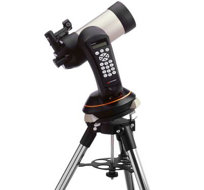
Celestron Nexstar 4 GT
The final piece of equipment is of course a laptop, which presumably most people have access to. Laptops screens are optimized to work in pretty bright ambient conditions, so their screens are correspondingly bright. Upon taking a laptop outside at night it quickly becomes obvious that the screen is far too bright, even on the lowest brightness setting. This totally ruins night vision adaptation and will be very annoying to any other astronomers near by. The solution is to place a piece of red acetate film over the screen which reduces the brightness to a level which does not negatively impact night vision adaptation. Some astronomy shops sell this pre-cut to the size of your laptop screen at vast expense. The secret to getting a deal is to know the word “Rubylith”. Type this into eBay and many vendors will appear offering the perfect material for the purpose. It is also suitable for use as safe-light protection in photographic darkrooms. A sheet for £4.99 was large enough to cover a large laptop, a small netbook, a smartphone and a little left over to make a red light torch.
Rubylith
Summary
To summarize the key pieces of equipment for doing planetary astrophotography on a low budget are
- Microsoft Lifecam Cinema HD – £20 from eBay
- Lifecam eyepiece adapter case – £16 from Billet Parts
- 1.25″ IR blocking/cut filter – £20 from eBay or other sources
- Bahtinov mask – £15 from Morris Engraving via eBay
- Rubylith sheet – £5 via eBay
- Laptop – any that can control the webcam.
- Telescope with tripod & mount – almost any, but Cassegrains are a good option for Planetary use. £200-300 for a second hand Nexstar 4, or £300-£350 for a brand new Skywatcher 127 which is a real bargain for what it provides – pretty comparable to the Nexstar in what it provides. Or pick from 100’s of other possible scopes.
The setup described above is suitable for imaging The Sun, to capture sunspots, but it is MANDATORY to have a protective filter in front of the telescope. These can be built using a sheet of Baader Astrosolar Safety Film for approx £20. For carrying all the kit around, skip the official cases and adapt a regular sports / holdall bag.
For a selection of the photographs I’ve produced using this setup, browse the ‘lifecamcinema’ tag on my Flickr profile