Serious astronomical imaging requires an equatorial mount for the camera / telescope, which tracks the rotation of the earth for anywhere between 5 minutes and several hours. Commercially available mount options have a starting price of several hundred pounds and range up to thousands. As a result many amateur astro-photographers choose the DIY option, building what’s commonly known as a “barn door mount“. At their simplest, they consist of two parallel planks of wood hinged at one side, with a threaded rod which is manually turned once a minute to gradually open the hinge at a rate which matches the speed of rotation of the Earth.
They are very simple to build, but the pain point should be clear from the end of the previous sentence – you need to control the dimensions such that one rotation of the threaded rod, causes the hinge to open at precisely the right rate. This isn’t as hard as it sounds for short exposures (10-15 minutes) but as the desired exposure time goes up the errors quickly spiral out of control. Some of the error is caused by construction inaccuracies but the bigger part is due to the inherent design decision to produce angular motion (opening hinge) from linear motion (rotating threaded rod). The latter is commonly referred to as the tangent error.
There are various more complicated barn door designs which use 3 pieces of wood to eliminate the tangent errors. Sadly the more complicated designs also increase the mechanical errors due to construction inaccuracies. The easy solution to this problem is to use a programmable microcontroller to drive the mount, allowing arbitrary errors to be corrected in software. When you need a cheap, low power microcontroller, the first option that comes to mind is an Arduino. A little bit of searching on google revealed someone who had built a barn door controlled by an Arduino Uno and a stepper motor. Even better, they provided a sketch of their circuit diagram for wiring it up.
Cost being king, I headed over to eBay to source the big ticket parts, and a maplin store for a few odds & ends I wanted to see in person before purchase. On the list were
Thus the total cost for the electronics was £46.21, a little bit higher than I was originally hoping for. I could have reduced it by going for one of the lower spec stepper motors which are bundled with a driver circuit board. This would have cut approx £12.00 off the cost, but I was not confident it would have sufficient torque for direct drive of the threaded rod, so I went for the sure bet. A pound or two could have been shaved off the cost of switches / power jack too, by sourcing from eBay instead of maplin. IOW it is probably possible to get the parts for about £30-35 if you really find the bargains. Before assembly the parts are laid out
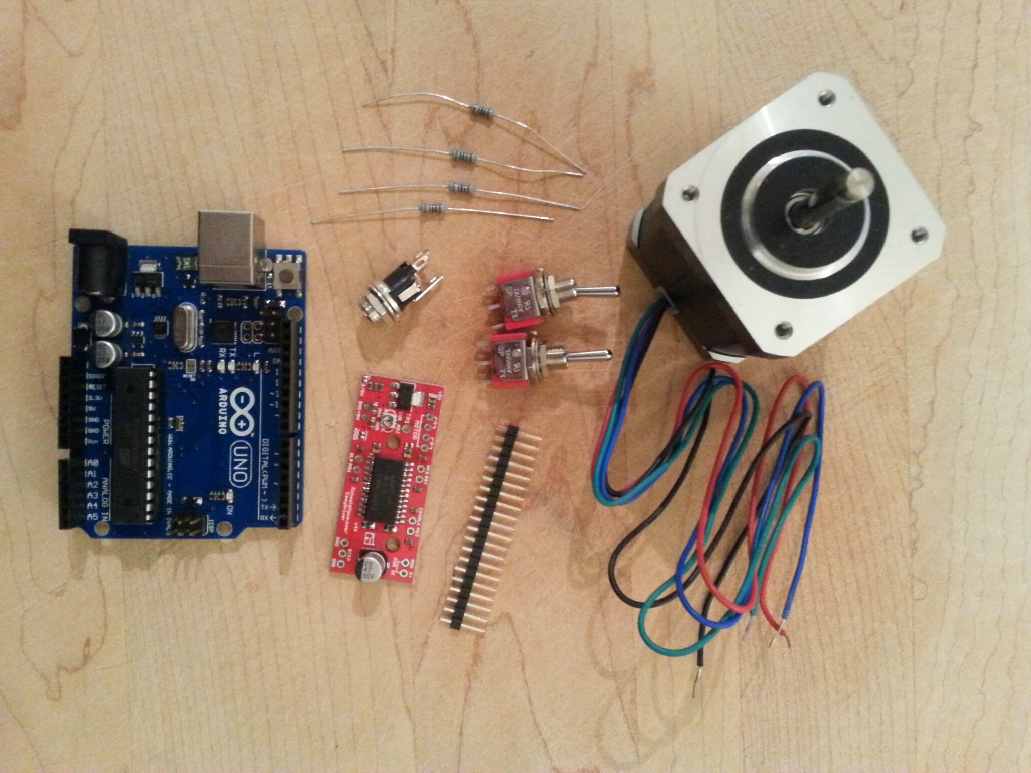
In addition to the project parts, you’ll need a few workshop items including a multi-meter, soldering iron, helping hands, wire cutters/strippers and 3A x 12v regulated bench power supply.
After looking at the previously mentioned circuit diagram, I decided to make one slight variation in the use of switches. I discarded the separate power switch, and used all three prongs from one of the switches to toggle between forward/stopped/backward. Thus the aim was to construct the following circuit diagram from the parts:
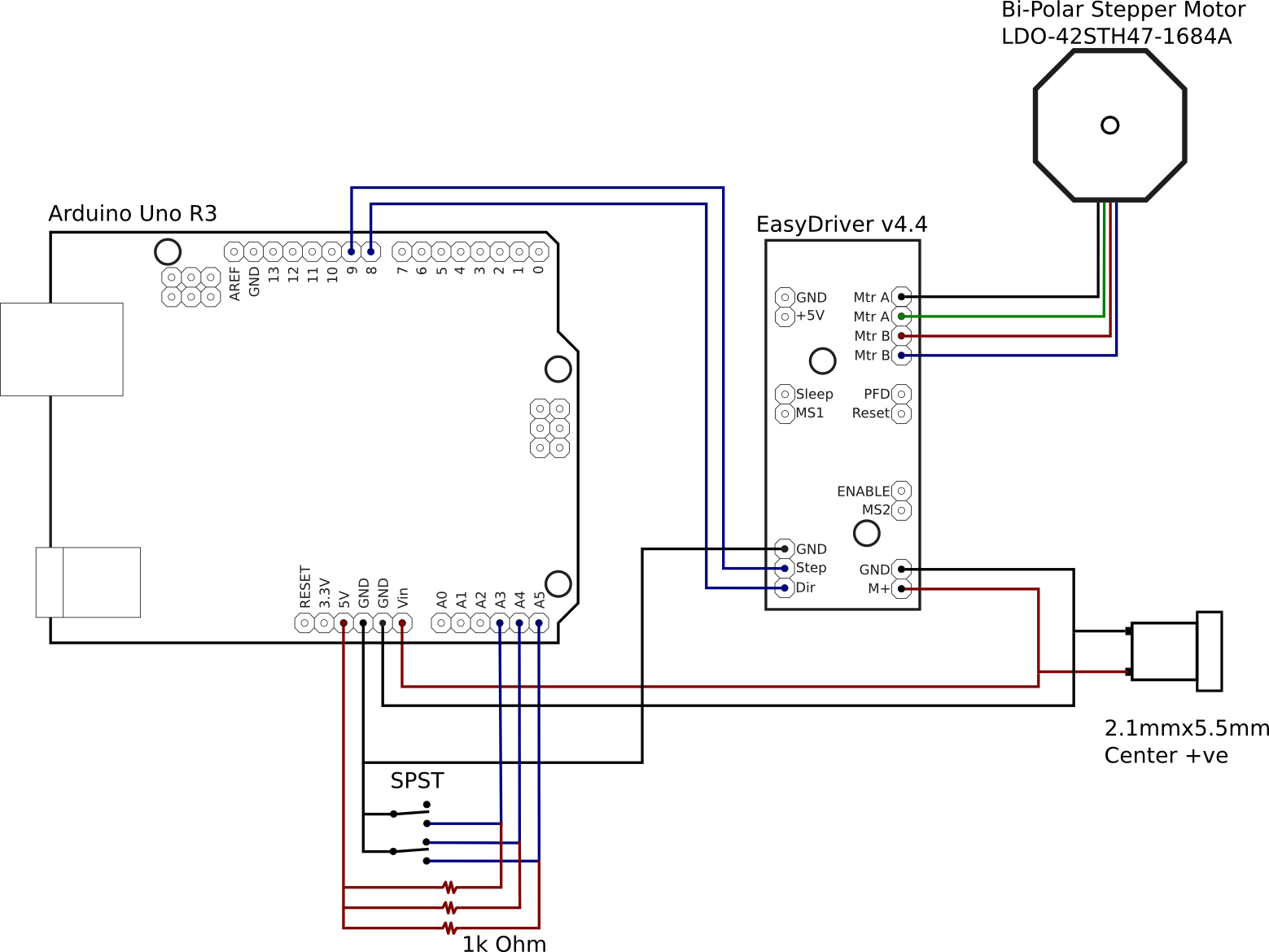
The Arduino is capable of being powered from the USB port, the on board DC jack, or the VIN pin. While the EasyDriver can take a 5v line from the Arduino board, this is only suitable for driving the electronics, not the stepper motor which needs much higher current than the Arduino is capable of supplying. Thus the decision was made to take a 12V supply from a off-board 2.1mmx5mm DC jack, to the VIN pin on the Arduino and M+ pin on the EasyDriver. The DC jack size was chosen to match that used on the Celestron NexStar telescope mounts, and so was wired center-positive.
The EasyDriver needs a minimum of two control signals, one to trigger a motor step and the other to set the direction of rotation. Thus the Step and Dir pins on the EasyDriver board were connected to the digital pins 8 and 9 on the Arduino. The EasyDriver defaults to 8-point microstepping. If use of full steps were required, the MS1 and MS2 pins could be connected to further digital pins on the Arduino. For the barn door mount though, the rate of rotation is so slow that 8-point microstepping is more than OK.
The two switches are going to be used to provide control parameters to the software running on the Arduino. The ON/OFF/ON switch is going to be used to switch the motion of the motor between clockwise, stopped and anti-clockwise. The ON/ON switch is going to be used to switch between automatic sidereal matched speed control and manual fast speed. For wiring, we effectively have a 1K Ohm resistor between the 5V output pin and an analogue pin. The switch is used to short this link out to ground. Toggling the switch thus toggles the analogue pin high/low.
The final piece of wiring is connecting the stepper motor wires to the EasyDriver. The ordering of the wires is absolutely critical. The stepper motor has two separate coils / phases, and 4 coloured wires coming out of it. Each pair of wires corresponds to one of the phases. The key is determining which wires match which phase and the polarity. Fortunately the stepper motor had a model number on it, allowing the data sheet to be located via google. The data sheet shows that one phase is connected to the black + green wires, while the other phase is connected to the red + blue wires. So the EasyDriver motor pins are wired up in the order black, green, red, blue. Again, this order is absolutely critical to get right – mixing up the polarity between the two coils will result in a motor which won’t turn. Likewise, not matching up wires within a phase will result in a motor which won’t turn. It is also NOT SAFE to use trial and error to test the motor while the EasyDriver is active. Detaching the motor wires while the EasyDriver is active will likely result in a burnt-out EasyDriver. Find the data sheet and get it right first time.
After a hour or two cutting and soldering wires the circuit was complete. To test it requires creation of a simple test program in the Arduino IDE. For this test I’d used the AccelStepper library instead of the Stepper library that is normally used, because the AccelStepper is more flexible to use.
#include <AccelStepper.h>

int debug = 0;

int dgPinStep = 8;
int dgPinDirection = 9;

int anPinForeward = 4;
int anPinBackward = 5;
int anPinSpeed = 3;

AccelStepper stepper(AccelStepper::DRIVER, dgPinStep, dgPinDirection);

void setup() {
  pinMode(anPinForeward,  OUTPUT);
  pinMode(anPinBackward,  OUTPUT);
  pinMode(anPinSpeed,  OUTPUT);

  stepper.setMaxSpeed(3000);

  if (debug) {
    Serial.begin(9600);
  }
}

void loop() {
  int valForeward = analogRead(anPinForeward);
  int valBackward = analogRead(anPinBackward);
  int valSpeed = analogRead(anPinSpeed);
  int run = 0;

  if (debug) {
    Serial.print("Foreward: ");
    Serial.print(valForeward);
    Serial.print(" Backward: ");
    Serial.print(valBackward);
    Serial.print(" Speed: ");
    Serial.println(valSpeed);
  }
  if (valForeward < 5) {
    if (valSpeed < 5) {
      stepper.setSpeed(200);
    } else {
      stepper.setSpeed(2000);
    }
    run = 1;
  } else if (valBackward < 5) {
    if (valSpeed < 5) {
      stepper.setSpeed(-200);
    } else {
      stepper.setSpeed(-2000);
    }
    run = 1;
  } else {
    run = 0;
  }

  if (run) {
    stepper.runSpeed();
  } else {
    stepper.stop();
  }
}
After compiling and uploading to the Arduino over USB, the program will start running immediately. If you’re not confident that the switch pins are connected in the right order the “debug” variable can be set to 1, which will let you watch the levels via the IDE’s serial console as the switches are toggled. Just remember to turn off debugging again afterwards because the println calls seriously slow down the program to the point that it is unusable in the real world. The video shows toggling the motion switch between forward/off/backward and the speed switch between slow/fast (sidereal rate is not implemented in the test program)
With everything working, all the remains is to house it in the plastic case. This required drilling a few holes for the switches and DC hack, and carving out a hole with a file for the USB port and carving a channel for the motor wires. With the electronics complete, the next phases are to build the mechanical side of the mount and then do the maths calculations and software programming necessary to track the earth’s rotation accurately. These will follow as separate blog posts in the coming days or weeks.
Now read: part 2, calculating mount movements
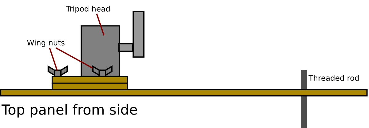
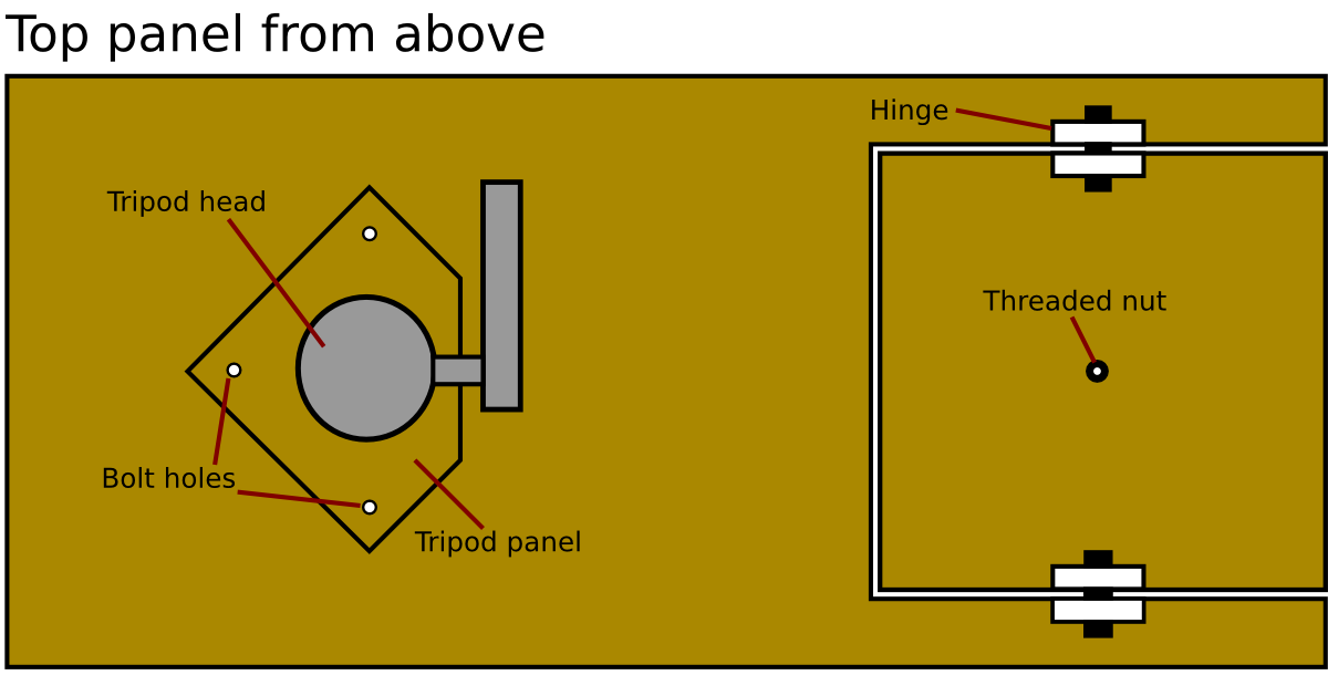 The tripod head attachment is better seen from the side view of the top panel. The tripod head could not be mounted directly to the main panel, because that would not allow sufficient clearance for the handle to be turned. So two small wooden panels were cut to raise the tripod head a couple of centimetres up from the panel. The tripod head is bolted to one of these small panels with a 3/8″ bolt, and both panels are then bolted down to the main panel using 3 bolts and wing nuts for easy release.